Product Support for: Accessories -> Throttle Holder (StowAway 4 Pack)
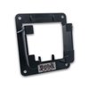
View the Product Page for the StowAway 4 PackBracket will hold: DT602, UT6 and other legacy Digitrax throttles. ▪ Access to LocoNet & Power Ports when stowed away. ▪ Stores throttle when not in use or when charging. ▪ Fascia mounted. ▪ Durable design. ▪ Easy to install. ▪ 90 Day Warranty On Materials & Workmanship Only.
434 Articles Found for StowAway 4 Pack

Bracket will hold: DT602, UT6 and other legacy Digitrax throttles. ▪ Access to LocoNet & Power Ports when stowed away. ▪ Stores throttle when not in use or when charging. ▪ Fascia mounted. ▪ Durable design. ▪ Easy to install. ▪ 90 Day Warranty On Materials & Workmanship Only.
DCS50 Zephyr - Quick Start Guide 1. Unpacking Your ZephyrUnpack your box and locate the DCS50 Command Station and the PS315 power supply. 2. Before You BeginBefore proceeding to the next step, make sure the Throttle Knob is turned all the way to “STOP” and the Direction/ Brake lever is set to “BRAKE”. 3. Connecting the Pieces TogetherOn the back of the DCS50, locate the gray screw terminal strip. On this strip, locate the two terminals labeled “RAIL A” and “RAIL B”. Attach your layout track wires to these terminals. It does not matter which is which. 4. Turn on ...
The Kato 4-8-4 FEF Steam Locomotive accepts the DN163K4A board replacement decoder. To disassemble the Kato 4-8-4 FEF, perform the following steps: 1. Gently slide the cab towards the tender. 2. Using a small Phillips head screwdriver, remove the screw located at the rear of the locomotive. 3. Slide the boiler toward the front of the locomotive. 4. Lift the entire boiler assembly off the chassis 5. Remove the plasic clip which is covering the analog circuit board. 6. Carefully remove both of the motor power tabs from the analog circuit board, being careful ...
The installation will be in the tender of the Con-Cor 4-8-4 locomotive. 1. Carefully remove the tender’s shell from the frame. 2. Remove the factory installed DCC dummy plug. (See photo below) 3. Insert the DN143IP medium plug pins in the socket. Pin 1 will be the bottom right socket when viewed. (See photo below) 4. Replace the tender shell. It may be necessary to trim the underside of the tender top to allow it to snap into place. 5. You are now ready to run your locomotive. The DN143IP is factory programmed to address 03. You can easily customize ...
Option # 4 sets the throttle ID of your throttle. Each throttle in your LocoNet system can have its own unique ID to support advanced LocoNet functionality. Products that use this feature will usually require each throttle in your system to have a unique ID.We recommend changing this ID only when specifically directed to do so by the manufacturer of a LocoNet compatible product that requires unique throttle IDs for operation. You may use any ID in the range of values x00-x7F (hex) and you must be sure that every throttle in your system has a unique ID #.
For Tower 55 and other locomotives that require 4 digit address to be programmed using CV17 & CV18 instead of the normal Digitrax Throttle Automated method.To determine the values to program into CV17 and CV18, please complete the following worksheet before beginning the 4-digit address programming procedure.1. Write the 4-digit address to be programmed into the decoder here: _____________2. Take the 4-digit address from step 1 and divide by 256. (Result from step 2 = ____________)3. Take the digits to the left of the decimal point in the result from step 2 and add 192. (Result from step 3 = ...
Am planning a 4 district layout with a Super Chief set. Can I serve all 4 districts with it using circuit breakers for each district? If not what do I need?In this case, the PM42 quad power manager can be used to give you circuit breakers in each of the 4 sub-districts.
Zephyr and systems using the DT400 will automatically program 4-digit address' with no math required. Those using other systems must manually program a 4-digit address. If you want to program a 4 digit address you simply cannot take the desired locomotive address and split the number and stick it into CV17 & CV18. The following example will NOT work: Locomotive 2345 CV17 = 23, CV18 = 45 – This isn’t how 4 digit addressing works. This method WILL work: Here is a simple method for figuring out what values belong in CV17 & CV18: The desired locomotive 4 digit address ...
Kato and Digitrax recommend the best DCC performance with the Unitrack turnout requires that you set each #4 turnout to "Non-power-routing". You can do this by changing the position of the screw that sets power routing which is located on the bottom of each #4 turnout. There are two screw adjustments on a Unitrack turnout, one for making the turnout non-power routing and the other being for setting either "live" or "insulated" frog (the point where the two rails cross)l Leave the frog screw in the "insulated" position.It should be noted that some N-scale Unitrack production has the routing/non-routing connections mislabeled, with the English-language ...
Option # 4 sets the throttle ID of your throttle. Each throttle in your LocoNet system can have its own unique ID to support advanced LocoNet functionality. Products that use this feature will usually require each throttle in your system to have a unique ID. We recommend changing this ID only when specifically directed to do so by the manufacturer of a LocoNet compatible product that requires unique throttle IDs for operation. You may use any ID in the range of values x00-x7F (hex) and you must be sure that every throttle in your system has a unique ID #.
In response to a request, here is a semi-official track plan of the Texas & Southwestern: The railroad uses Kato Unitrack: 249mm radius curves 282mm radius curves Seven #4 Right turnouts, configured to be "non current routing" Five #4 Left turnouts, configured to be "non current routing" Two 90° crossings A variety of straight tracks, including the 20-091 Short Track Assortment Three 20-050 Adjustment Tracks Several 24-818 Terminal joiners to supply power to the railroad and to connect the AR1 to the reversing segment Insulated Unijoiners were used to define the reversing segment. Alert readers will note that the tracks ...
CV29 is assigned a single value which chooses a combination of specific effects: 1. Speed step control. 2. Speed table On or Off. 3. Analog mode conversion On or Off. 4. Normal Direction of Travel (NDOT). 5. 2 digit addressing or 4 digit addressing. 2-digit or 4-digit Addressing The decoder's address is the identification number programmed into specific decoder that lets that decoder recognize commands sent to it by the command station. Once you program the decoder's address, it will be remembered in the decoder until you re-program it. All Digitrax current production decoders can be set up with ...
Note: The programming shortcut for 4-digit addressing outlined in the Digitrax Zephyr manual will not work to program the Tower 55 decoder in any programming mode on the Zeyphr throttle due to a programming timing issue with the DSC50. Please use the procedure referenced in this bulletin to access this feature.Note: If the DCS50 or DCS51 is being used as a command station with a DT400/DT400R throttle connected via the Loconet ports, then the programming shortcut for 4-digit addressing outlined in the DT400/DT400R throttle manual will work to enable the 4-digit address capability of the decoder when using the DT400/DT400R throttle ...
The layout uses twenty-eight turnouts on the mainline and an additional eleven turnouts in the yard. Each turnout is powered by a Tortoise slow motion turnout motor. Each of the twenty-eight mainline turnouts has three dwarf signals associated with it. The aspects of the signals are shown below. The indications of the signals are: Green = Proceed Yellow = Proceed with caution Red = Stop Each signal has one head with two LEDs. There are also thirty-eight mainline block signals (red/green) that are controlled by heavy duty single pole double throw relays. This makes a total of 122 signals. Since ...

3 Pack Edge Connector for use with PM4 Series Boards, BDL16 Series Boards and SE8 Series Boards This is a replacement part that can be ordered through your dealer. Digitrax does not repair this item or sell directly to end users.


Use for joining LocoNet Cables, adding coiled cords to throttles, etc.

Use to make custom LocoNet cables & repair broken plugs.

Digitrax Dummy Plugs for analog operation of Digitrax Easy Connect harnesses (5 pack)

Digitrax 9 pin to bare wire harnesses in 5 packs

5-Pack Dummy plug for Digitrax N scale Harness system

5-pack Digitrax N-Scale Wire Harness

Nickel-Metal Hydride 600mAH 3.6v Rechargeable Battery Pack.


For use with BDL716, BDL16 Series Boards, BD4N, and other products.
Sound Decoder: SDH164D SoundFX Wired Mobile Decoder fopr HO Locomotives Master Volume: CV58=9 to 15, Diesel CV60=1, Bell CV141=64Max., Horn CV142=64 Max. Speaker: 4 inch Dia. 8 Ohm Speaker, 4 Watts with a 3.3 Ohm resistor in series. Diesel Horn 880Tone Sine Wav. Horn & 880 Hz together Factor dB@4' CV58 MtoP dB@4' CV58 MtoP dB@4' CV58 MtoP x 0.71 79 15 3.85 74 15 4.00 79 15 4.00 2.84 Vrms 78 12 3.80 73 12 3.95 Amplifier ...
DCS50’s Jump A & B ports can host two DC power packs that work as additional throttles to control DCC locomotives.You begin with an operating DCS50 attached to your layout. In addition to the throttle built into the DCS50, you can create a LocoNet to add additional Digitrax throttles and other Digitrax devices. Jump Ports:You can also connect up one or two smooth DC power packs as shown in the following illustration. These power packs must also be powered, since the Zephyr jump throttle connections detect the voltage level from the individual power pack(s) and makes adjustments to the command control ...
Q: I have an MRC RailPower 1370 DC power pack. I was wondering if that would work as a jump throttle on my Zephyr till I get my UT4 LocoNet Throttle? A: We think that the answer is "No", but you will need to verify whether this power pack produces pure or pulsed DC power directly with MRC. Throttles used with Zephyr Xtra via the Jump Port must produce pure DC power, often referred to as "smooth" power packs. Many "advanced" analog power packs use automatic pulse injection to make model locomotives run better at slow speeds. This uses 1/2 wave AC ...
The term smooth DC is used to describe the power provided to the layout by conventional model railroad power packs (analog transformers). Traditional model railroad power packs convert household line current into 12-18 volt current to power your model railroad. Voltage is supplied to the track, and as the voltage increases, the speed of the locomotive's motor increases, which makes it run down the tracks at faster speeds. Some power packs put out only AC (alternating current), while others put out DC (direct current) and AC (for accessories such as track switches and building lights). AC powered trains tend to ...
Here are some terms that you might find useful as you work with the BDL168. Direct home wiring is a layout wiring method where each power district and its booster is electrically isolated. The track within each power district uses a "common return" wiring method for occupancy detection and/or power management. Direct home wiring is the wiring method recommended by Digitrax for safety reasons & also because it makes detection work more prototypically. Power district is the power wiring, track, components and equipment attached to that wiring, driven by a single properly isolated booster. The track for a power district ...
What's the best method to handle structure and street lighting with a DCC layout? If I put in bus wiring for my lighting can it interfere with the DCC signal? Unless you have stationary decoders that control the structure and street lights, there is no need for connecting these lights to your DCC wiring. In fact, doing so will add additional power consumption without any of the advantages of command control. These additional power consumers take away available power for your locomotives, controlled cars and stationary decoders. Should I use a completely different power source like an old power pack? ...
Note: Zephyr (DCS50) has been superseded by Zephyr Xtra (DCS51) which is available in an EU version that comes with the appropriate power supply. This article only applies to the original Zephyr (DCS50)Q: I´m a foreign model railroader, and I want to buy a Zephyr without power pack. The instruction manual says that I can use a 18 Volt DC trafo in order to power the Zephyr. Can you suggest a way to connect a Zephyr DCS 50 to German current (220/50)? A: In the North American market, Digitrax recommends the use of a dedicated PS315 power supply or equivalent for use ...
Stall Current is the max current draw in amps for a motor when it is stalled. This is important in determining which decoder to install in a locomotive. Why is Stall Current important? In the conversion of analog locomotives to DCC, how much current the locomotive draws is a major factor in decoder selection. Decoders are grouped by their ability to handle the electrical load that flows through them to the locomotive motor. The Ampere (Amp) is the unit of measure for electrical current used by the locomotive. The current draw of most HO can motors is between .5 and 1.5 ...
I have a 4x8 H0 scale layout. I'm 13 years old and REALLY thinking about switching to DCC, I need to know really fast because I want to ask my parents to get it for Christmas.You wouldn't know by looking at those who edit the Tech Support Depot, but there actually was a time when we too were thirteen, and just starting out in model railroading. In many ways, we still are thirteen years old; we just can't move as fast. Consider this photograph from our youth: This little bit of ancient model railroad history dates back to the 1950's, ...
The PS615 is the Digitrax recommended power supply for the DCS240 in 5 amp mode. For operations at 8 amps the PS2012 is the recommended power supply. When using the PS2012 special wiring considerations need to be used when powering both the DCS240 and legacy boosters from the same PS2012. Leagacy boosters are defined as the DCS100, DCS200, DB150, DB200 or DB100. Please see the separate article “Powering your DCS240 with a PS2012” and the additional notes below. The DCS240 may be powered either using the barrel plug connector or the screw terminals labeled “+” and “- “. The barrel ...
Digitrax Complete Train Control By Zana & A.J. Ireland Digitrax Complete Train Control makes reliable, realistic train operation and simplified layout wiring a reality. Digital Command Control is incorporated within the Digitrax system to let you control multiple trains independently on the same section of track without blocking. In the real world, engineers control the speed and direction of real trains. Engines operate under their own power independent of the track. Each engine has its own motion characteristics like how fast it speeds up (acceleration) and how long it takes to slow down (deceleration). A locomotive's performance is influenced by ...
CV29 is called the configuration register. It controls the following decoder characteristics: 1. Whether the decoder uses 14 speed steps, 28/128 speed steps or loadable speed tables. This affects how smoothly the loco will move and how it responds to throttle controls.2. Whether the decoder automatically converts to analog mode when no DCC signal is present. This allows the decoder to operate on a DC layout even though it is DCC equipped.3. Defines the normal direction of travel for the locomotive. Normal Direction of Travel or NDOT can be changed when the motor connections of decoder have not been connected so that the locomotive runs ...
This article stops in a strange place?? We need to find the rest of it and split it up into meaningful chunks. Also needs meta stuff Troubleshooting in General:Regardless of the guides, manuals, tips, suggestions, experts or whatever, troubleshooting can occasionally degenerate into a vast chasm of darkness and confusion. It would be impossible to cover all the areas that have, can or may cause problems. This is a general guide to identifying and resolving problems with Digitrax Complete Train Control. Keep Good Records:Although it may seem to be a pain while setting up your Digitrax system, keeping layout records ...

Cost effective N and HO sized decoder with integral DCC medium plug

Board Replacement Decoder for Kato N-Scale Glacier Express

Drop In Mobile Sound Decoders for Kato N scale Locomotives

SDXN147K4 Sound Decoder

When used in conjunction with the DS64 or SE8C the BD4 provides LocoNet detection for 4 occupancy detection sections. BD4 lets you know which detection sections of your layout are occupied by locos and rolling stock. Not recommended for layouts using "supersonic" decoders unless the "supersonic" feature is turned off in all decoders.

4 Amp Digital Command Control Mobile Decoder for Large Scale locomotives Retired in 1994

DG83FX 4 Amp Mobile Decoder for large scale locomotives Retired in 1998

Series 5 HO/O Wired Decoder Decoder Lock equipped Series 5 Decoder has Full Series 3 Mobile Decoder Feature Set plus Sound Bug ready

1 Amp Digital Command Control Mobile Decoder Retired in 1997

1 Amp Wired Mobile Decoder, 4 Functions Technical Note: If using DH142, DN142, DN141K2, DN149K2 series decoder, when F1 is set up for FX, F2 must also be set up as FX (It can’t be used as standard on/off function.) If you want to use a combination of FX & standard on/off functions, please use F1 as the standard on/off function and F2 as the FX function. Retired in 2006

1 Amp Mobile Decoder with DCC Medium Plug on Short Harness Retired in 2006

Tiny wired decoder for many Z, N & HO Applications.

Tiny 4 FX3 function decoder with DCC medium plug and 1" harness

Fits Many N and HO Locomotives

The UT4 is designed for simple control of trains and their functions. Operators worldwide told us what they wanted in an affordable, easy to use "operator's" throttle and we made their dreams come true. The UT4 is perfect if you're looking for a "traditional" style throttle. They are ideal for operating sessions and are great for novice users as well.

The UT4D is designed for easy to use Duplex radio control of trains and their functions. Operators worldwide told us what they wanted in an affordable, easy to use "operator's" throttle and we made their dreams come true. The UT4D is perfect if you're looking for a "traditional" style throttle. They are ideal for operating sessions and are great for novice users as well.

The UT4DCE is designed for easy to use Duplex radio control of trains and their functions. Operators worldwide told us what they wanted in an affordable, easy to use "operator's" throttle and we made their dreams come true. The UT4DCE is perfect if you're looking for a "traditional" style throttle. They are ideal for operating sessions and are great for novice users as well.

The UT4R is designed for simple radio control of trains and their functions. Operators worldwide told us what they wanted in an affordable, easy to use "operator's" throttle and we made their dreams come true. The UT4R is perfect if you're looking for a "traditional" style throttle. They are ideal for operating sessions and are great for novice users as well.

The RX4 is a 4 zone transponder detector for use with Digitrax occupancy detection systems. The RX4 enables you to not only see what blocks are occupied but also identifies what is there.

Early Digitrax Universal Panel makes hookup, maintenance and troubleshooting of your LocoNet network system simple. The UP1 provides 2 RJ12 Plugs, One 1/4" stereo jack, and one 5pin DIN connector. The UP1 has indicator LEDs that show activity on the LocoNet network & monitor the power state of a local track section. Retired in 2000

Low-cost, High-sensitivity DCC block-occupancy detection.

Power Manager with Occupancy and Transponding detection for 4 sub-districts.
OPS Mode Programming Soundtraxx Tsunami Sound Decoders This article was originally written for Soundtraxx Tsunami decoders. It will also work for other manufacturer's sound decoders. The individual CVs that make up an address will need to be programmed individually. These CVs are AD1, CV17, CV18 and CV29. AD1 is the Primary (short address) Default 03, Acceptable Values 1-127 CV17, CV18 are the two CVs that make up the Extended (long address), Acceptable Values 128 - 9983 CV29 is for Decoder Configuration. Values are 06 for 2-digit and 38 for 4-digit addressing. There are many other values that ...
By Zana & A.J. IrelandThis clinic is titled Digital Command Control: The Wave of the Future. Recently, I was asked the question: "DCC has arrived and is the technology of today, everybody's using it so, why don't you change the title of your clinic?" My answer is that digital command control is still evolving rapidly. Today's digital command control is moving beyond the basic NMRA DCC Standards and RPs to encompass many new technologies that will compliment and enhance the basic things we can do with the track format defined by the NMRA. It's an exciting time for model railroaders ...
By Zana & A.J. IrelandThis clinic is titled Digital Command Control: The Wave of the Future. Recently, I was asked the question: "DCC has arrived and is the technology of today, everybody's using it so, why don't you change the title of your clinic?" My answer is that digital command control is still evolving rapidly. Today's digital command control is moving beyond the basic NMRA DCC Standards and RPs to encompass many new technologies that will compliment and enhance the basic things we can do with the track format defined by the NMRA. It's an exciting time for model railroaders ...
Editor's Note: This tech note has nothing to do with Digitrax SoundFX sound decoders. This is for users who have Digitrax command stations / boosters / etc and wish to program MRC sound decoders. --------------------------- Due to low programming track power in certain dcc systems, programming sound decoders on the program track may not be possible, especially trying to assign the decoder a four, (4), digit address. This programming procedure has to be performed on the mainline, where more power is available for programming sound decoders. If your dcc system allows simple 4 digit address programming on the main, [ops mode ...
IPLING From time to time the latest DT602 family throttle firmware will be updated and will be posted on the product support page. These updates may slightly modify the DT602's operation, based on customer feedback/requests and priority support issues discovered. If you are happy with the operation of your DT602, and have no issues or new features you may want, it is not required to perform an available update. All DT602 family throttles should only be firmware updated or IPL'd while plugged directly into a working LocoNet. The Digitrax provided DMF file for field updating DT602's can be used for IPL of any ...
Some DCC systems need to have CV's 17 and 18 programmed separately to assign the decoder a 4 digit address.Digitrax command stations handle this automatically by default. If you have a decoder that needs manual entry of CV17 & CV18, follow these steps:You cannot simply split the four digit address in 2 halves and input these into CVs 17 and 18. A conversion from decimal numbers to hexadecimal numbers is required. Once the hexadecimal conversion for the 4 digit address is performed, this number is then split in half and then each half is input into CV17 and CV18 respectively.To ...
Duplex Radio Throttle do not need to be plugged in to LocoNet to Program Decoders. Simplex Radio & Infrared throttles must be plugged in to LocoNet to program CVs on the programming track. Ops Mode Programming can be done without plugging radio throttles in to LocoNet. IR throttles must be plugged in for Ops Mode Programming. 1. Be sure that only the loco you want to program is on the programming track. If you are using operations mode programming, the loco you want to program can be anywhere on the layout but it must have a decoder that is ...
The Digitrax DS51K1 Stationary Decoder is for use with single coil Kato powered turnouts only. These turnout include the following: 20-202 N Scale #6 Left Hand Powered 20-203 N Scale #6 Right Hand Powered 20-210 N Scale Double Crossover Powered * 20-220 N Scale #4 Left Hand Powered 20-221 N Scale #4 Right Hand Powered 20-222 N Scale #2 Wye Powered 2-860 HO Scale #6 Left Hand Powered 2-861 HO Scale #6 Right Hand Powered 2-850 HO Scale #4 Lef Hand Powered 2-851 HO Scale #4 Right Hand Powered * The 20-210 Double Crossoever requires a total of 4 DS51K1 ...
If you have more than four turnouts, you will need to program the addresses.The DS64 has 4 Output pairs labeled 1R & 1G, 2R & 2G, 3R & 3G, and 4R & 4G. The DS64 is shipped from the factory with these outputs programmed as Switch Addresses 01, 02, 03, and 04 respectively. You can set the Switch Address of each of these four Outputs to any value from 01 - 2048.NOTE: During this procedure the DS64 must be connected to an active LocoNet with an active command station.1. On the DS64’s control panel, press and hold the ID button ...
Digitrax UT4D Throttle Operating Instructions by Dan Bourque v1.0 Selecting a locomotive or consist 1. Dial the 4-digit locomotive address into the “LOCO ADDRESS” dials - For a consist, the address will normally be the lead locomotive - For a 3-digit locomotive number, use “0” for the first digit 2. Press the “SEL” key, the ST light on the throttle should flash green 3. Move the direction selector on the throttle to either “R” or “F” 4. Move the speed knob until train moves 5. For headlight, press the “F0” key (“F3” will ...
Q: I connect my DT400 to my DCS100 and it works fine, but when I add a DB150 working as a booster the DT400 stops working. What is wrong? A: A number of things may cause this, so you can use the diagnostic features of the DT400 to solve this problem. Experience has proven that the most common LocoNet problem is related to pins 3 and 4. By following this diagnostic procedure, you can narrow down to the source of the problem. Starting with DT400 without a battery [The throttle has no battery for this test to assure it executes ...
Digitrax uses CV33-CV46 to handle remapping according to published standards.The CV values that are permitted for function remapping are limited to 8 bits, a maximum value of 255. Therefore only 8 functions can be mapped to each function key.Function remapping is easy! Just follow these simple steps:1. Locate the row for the Throttle Function Key [chart below] that you want to use.2. Locate the column of the Function Lead Color (number) you want to control.3. Note the value at the intersection of the row and column.4. Program that value into the the CV listed next to the Throttle Function Key. ...
DT402 & DT400 Series Throttle-Locomotive Recall The DT402 & DT400 Series Throttles store the last 4, 8,or 16 unique loco addresses used by the throttle in a recall stack; your throttle defaults to a 4 address recall stack. Users often discover this feature when taking their throttle for use on another Digitrax railroad; they plug their throttle into the new LocoNet and discover their own locomotive addresses are still in their throttle. The presence of stored locomotive addresses may make operations on your railroad easier.For example if you have your throttle set up for an 8 deep recall stack and the last 8 ...
Overview:To reset locomotive electronics to factory defaults the user must set CV08 to a value of 08. It is recommended that this procedure be performed on the dedicated service mode programming track using direct mode programming.* Note: This is the only programming procedure that we recommend using the programming track for. All other programming should be performed on the main track using Operations mode programming.Procedure:1. Place the DCC equipped locomotive on a dedicated service-mode programming track.* Note: The rails of this track should be connected to the PROG A & PROG B outputs on the DCS100 command station.2. Set the ...
Digitrax UT4 Throttle Operating Instructions by Dan Bourque Selecting a locomotive or consist 1. Dial the 4-digit locomotive address into the “LOCO ADDRESS” dials - For a consist, the address will normally be the lead locomotive - For a 3-digit locomotive number, use “0” for the first digit 2. Plug the throttle into any receptacle on the layout fascia (e.g. Digitrax UP5) 3. Press the “SEL” key, the ST light on the throttle should turn green 4. Move the direction selector on the throttle to either “R” or “F” 5. Move the ...
You can easily control sound units like the Keller SU1990 by using the function leads on Digitrax Decoders and DCC command station that can control decoder functions. These instructions for connecting a Keller Engineering Diesel Sound unit to Digitrax DH83FX & DH140 series decoders was writtne many years ago. Any modern Digitrax decoder with 4 function leads can be used. Equipment Needed:1) A Digitrax Throttle, Booster/Command Station or other DCC command station capable of controlling decoder function outputs.2) Any Digitrax decoder with at least 4 function leads will work here.3) The locomotive you wish to convert, be sure to check the ...
DS64 Quad Stationary Decoder The DS64 is a Stationary Decoder for use with 4 slow motion, solenoid, or bi-polar turnout machines Simple to hook up and configure Controls 4 individual turnout machines: EITHER4 Slow motion turnout machines, such as TortoiseTM by Circuitron or SwitchmasterTMOR4 Solenoid-type turnout machines such as three wire (twin coil type) Peco or Atlas Snap Switches or two wire bi-polar type turnout machines such as Kato Unitrack, AristoCraft, or LGB turnouts with capacitive discharge capability Support for up to 8 routes Screw terminals make installation easy Use with any LocoNet Compatible System ...
This Application note shows how Marklin Users can have the power and reliability of Digitrax boosters along with their Marklin command stations! Notes: 1. Before applying power to the booster, use a short length of wire to short the 2 gray terminals (SYNC & GROUND) on the DB100. This forces the DB100 into the booster mode when the power is applied to it. Set the MODE switch to "P/R" for auto reversing operation or to "RUN" for normal booster operation. 2. Make a cable with 6 conductor RJ12 cable with a 6 conductor male plug on the DB100 end and ...
If you are NOT plugged into a LocoNet port1. Use the 4 rotary address selector knobs on your UT4 to dial up the 2 or 4 digit address of the locomotive you want to run. To enter a 2-digit addresses, set the first two selector knobs to 0 and enter the two digit address on the 2 address selector knobs on the right hand side of the throttle (for example 0025).2. Plug the UT4 into any LocoNet port and automatic selection occurs.3. A Green Status light confirms that selection has been done successfully - You’re off and running!4. A Red Status light means the loco is ...
Note: This page applies only to Challenger SetsOur customers continue to come up with different combinations & configurations to suit their individual needs so, feel free to customize your own CTX/CTY!Some users choose to hard wire 4 throttles for the 4 different channels so that the throttles are not able to change locomotives within the group.Parts List:Radio Shack Part NumbersSW-1: 6 Position Rotary Selector Switch, # 275-1386, CTX 1, CTY 1C1-C4: 0.047uf Disc Ceramic Capacitors 50v, # 272-134, CTX 2, CTY 2D1-D5: 1N4148/1N914 Small Signal Diodes 50v/100ma, # 276-1620, CTX 1, CTY 2SW-2/SW-6: Normally Open Push Button Switch, # 275-1566, ...
CTX/CTY throttles allow you to have up to 4 separate throttles controlled by 4 different operators rather than 4 throttles controlled by one operator as in the CT4 that comes with your Challenger Set. Digitrax provides these instructions so that you can build your own throttles to your own specifications. You are free to choose any knobs, buttons & cases you like, the ones on the parts list below are just suggestions. These throttles give you the option of expanding your operations cost effectively. The CTX throttle controls speed & direction for one train in the operating group & can ...
DT400/R’s are shipped from the factory with tetherless release disabled. This prevents you from accidentally touching the LOCO Key and entering address selection while you are running your throttle in tetherless mode. DT400 can be set up to allow locos to be released from the throttle when it is in tetherless mode (IR or radio) by setting DT400 Option #3 according to the following table. Op#3 Value (hex) Backlight Brightness Clock Format Recall Stack Depth Tether- less Release x00 Off 12 hour format 4 No x01 Low intensity 12 hour fomat 4 No x02 Medium intensity 12 hour format 4 ...
The following CV settings have been found to give great performance from the Trix Mikado. These settings were discovered by Norm Stenzel after much trial and error. Once the loco was set with the following CV values this locomotive operated very nicely with the sound synchronized to its movement. CV 2 = 4 Default Value = 4 START VOLTAGECV 3 = 0 Default Value = 8 ACCELERATIONCV 4 = 0 Default Value = 6 DECELERATIONCV 5 = 35 Default Value = 64 MAX VOLTAGECV 6 = 20 Default Value = 22 MID POINT VOLTAGECV 29 = 6 Default Value = 4 CONFIGURATION ...
1. Choose which THROTTLE knob (L or R) you want to use to run a locomotive. Make it the active throttle by turning the throttle knob a 1/4 turn in either direction or by pressing down on the knob.2. Press the SEL key. The active throttle display will begin flashing the Loco Icon, the last loco address selected on the throttle and the Lo mode indicator. Sel loco will be displayed in the Text Area of the LCD display.3. To select a 4 digit address, rotate the L THROTTLE knob to dial up the first two digits (1000s and 100s) of ...
Testing for Tower 55 DCC Equipped Locos after 4 Digit address programming:Note these instructions are the same for both DCS50 Zephyr and DCS51 Zephyr Xtra1. Press the LOCO key on the DCS50. (The LED display should begin flashing)2. Enter the 4-digit address that was programmed in the procedure above using the numeric keypad. (The LED display should be flashing “####” with the # symbols replaced with the 4-digit address that was keyed in)3. Press the LOCO key on the DCS50. (The LED display should display “####” solid and the locomotive sounds should start up)4. Select FORWARD with the direction knob ...
What is the physical size of the BDL168? The board itself approximately measures 3 3/4" wide by 3 5/8" long by 1 1/4" high. For those who use metric, it is 94mm by 92mm by 30mm. In addition to the board itself, the edge connector measures 4 1/32" (112mm) by 3/8" (10mm); it has edge connector pins which make the connector 5/8" wide (18mm). The edge connector pins will need additional clearance for the connected wires. Users have found that the heavier bus wires used in most applications are difficult to connect to the edge pin connector; in ths situation, ...
Overview: Broadway Limited has issued a new line of H0-Scale locomotives called "Blueline". These locomotives are equipped with sound decoders that can be operated in a conventional Direct Current environment. They also are fitted with an 8-pin DCC Medium plug to allow for conversion to a DCC operating environment. Among other decoders, Broadway Limited recommends using our DN143IP mobile decoder for this purpose. Converting these locomotives is simple, but programming a 4 digit address can be a challenge. BLI has a support page which indicates that changing the locomotive address and other CV's can be done in OPS Mode (also ...
Flashing ditch lights can be set up with several CV's. Using 1.5 Volt Bulbs or LEDsIf you use 1.5 V bulbs, you must install a current setting resistor with a minimum value of 100 ohms for each bulb.Typically a 560 ohm 1/4 watt resistor works well for a grain of rice bulb and a 250 ohm 1/4 watt resistor works well for a grain of wheat bulb.Lower resistance values will increase the lamp brightness. If you use LED's be sure the polarity is correct when you hook them up & install a current setting resistor for each LED. Typically a ...
1. Before using your TL1, set its address. This may or may not be the same address as a mobile decoder already installed in the loco or car depending on how you are planning to use the TL1. In the case of TL1s being used as a stand alone transponder or as a function decoder, choose an address that is not associated with another mobile decoder address in use on the layout.2. Connect the RED & BLACK wires of the TL1 to a service mode DCC programmer and program the TL1's address as you would any mobile decoder address.Follow the ...
A cascaded route is where the last command of a route triggers the next route; this is also known to some as a nesting route. With the capacity of 8 turnouts per route, it becomes necessary to cascade routes if more than 8 turnouts are involved in a route. To highlight these possibilities, we use a very complex scenario with many turnouts and possible routes. Cascading routes allows the setup of long routes without the need for a computer. Since some routes exceed the capacity of 8 turnouts, the remaining turnouts of the long routes are setup in the second ...
To run a locomotive, you must first select it.1. Choose which THROTTLE (L or R) you want to use to run a locomotive. Make it the active throttle by turning it a 1/4 turn in either direction or by pressing down on the knob. If there is no active address selected to the throttle, as shown above, SEL will blink to let you know that the throttle is ready to select an address.2. Press the SEL key. The active throttle display will begin flashing the Loco Icon, the last loco address selected on the throttle and the Lo mode ...
Program the TF4's Address & Function Outputs1. Before using your TF4, set its address. This may or may not be the same address as a mobile decoder already installed in the loco or car depending on how you are planning to use the TF4. In the case of TF4's being used as a stand alone transponder or as a function decoder, choose an address that is not the same as another mobile decoder address in use on the layout.2. Connect the RED & BLACK wires of the TF4 to a service mode DCC programmer and program the TF4's address as ...
The UT4 comes InfraReady for layouts that are equipped with one or more UR90 infrared receivers. For Infrared operation:1. Install one or more UR90 infrared receivers on your layout. These should be connected to LocoNet and powered. If you have UR92s and/or UR91s present on the layout, these also support infrared operation. You will need enough infrared receivers installed on the layout so that the throttles you use can "see" the receivers since the transmission is line of sight. You may also encounter problems in rooms where there are large windows that would interfere with the transmission.2. Install a 9 ...
This article courtesy of Ross Webster, which dates from an earlier era before Bachmann made accommodations for DCC installs:There may be others ways do to this conversion, but this is the way I found using the Digitrax DG380 (any DG wired decoder can be used for this installation) DUE TO SOME OF THE FRAGILE ITEMS ON THE SHAY I WORKED ON A FOAM PAD SO THERE WAS NO DAMAGE TO ANY OF THE SMALL PARTS.I first tested the electrical items and made the following determinations.Free running for the two trucks was .8 amps, total. Stall, was 4.6 amps total for both trucks. Smoke ...
To change DT400 Option Settings 1. Consult the Throttle Option Setting Tables found in the DT400 manual to determine which settings you want to make for each of the 6 available options. 2. Press the OPTN t Key and the display will show: 3. The right side of the display will show the current value for OP#1. The default setting for OP#1 is x01. Notice that these values are entered in hex format. The “x” in front of the value lets you know to expect to use hex numbers. Pressing the throttle keys will not change to decimal values in this ...
Many operators use a fast clock during operating sessions to simulate prototypical operations. Traditionally, this clock is on the wall and is set up to run at a faster than normal rate. LocoNet has its own networked fast clock for all Digitrax throttles connected to your system.To use the Fast clock feature of the DT300, you must be plugged into a Digitrax command station.When there is no activity on your DT300 for more than about 6 seconds, the DT300 will revert to the default display. Your DT300 was shipped with Lo (Loco) mode, showing the current speed of selected loco(s), ...
Digitrax DCS50 (Zephyr) Operating Instructions by Dan Bourque v1.0 Selecting a locomotive or consist 1. Press the “LOCO” key (display will flash) 2. Enter the address of the locomotive or consist - For a consist, the address will normally be the lead locomotive - For a 3-digit locomotive number, use “0” for the first digit 3. Press the “LOCO” key again (display will stop blinking) 4. Move the direction selector on the throttle to either “Forward” or “Reverse” 5. Move the speed knob until train moves Dispatching (releasing) a locomotive or consist 1. ...
1. The UP5 Universal Panel is designed for mounting on the fascia board of the layout. Cut a hole approximately 2.5” W x 1.5” H in the fascia board. Insert the UP5 through the hole with the face plate on the front of the fascia board. Attach the UP5 face plate to the fascia board with four #6 screws. Note: The UP5 uses the black screws to mount the front fascia plate.2. Connect the UP5 to LocoNet using pre-tested LocoNet cables. There are 2 LocoNet Jacks located at the back of the UP5 board for connecting LocoNet devices on your layout. ...
The DCS100, 200, 240 and DB150 use several beeps and clicks that can be used as diagnostic tools that will help you debug a number of error conditions. DCS100/200 Audible Sounds 1 Beep DCS100/200 has powered on successfully or has sent a programming command. 3 Beeps A loco address has been "purged" due to non-use. This is informational only and is normal. 4 Beeps Booster short circuit shutdown. Fault Alarm. 6 Beeps Command station already present in system. When two command stations are operating on the same system, you may experience unexpected results. 7 Beeps DCS100/200 CMOS battery low ...
1. Carefully remove the locomotive's shell from the frame. Notice the orientation of the circuit board inside so that you can install the decoder in the same orientation. (Figure 1) 2. Remove the 10 black plastic plugs from the lightboard that secure the wires to the PCB. There are 4 plugs (retainers) on each end and 2 on the side for the motor connection. Remove the red and black wires, carefully noting where each wire originally connected to the PCB. Remove the lightboard itself by pinching the black plastic release tabs and pulling the board up and off of the ...
Note: DT300 radio or infrared versions must be plugged in to LocoNet to edit the fast clock settings.1. From Lo (Loco) mode, press the MODE key to change to Sw (Switch) mode.2. Press the FN/F0 key to change from Sw (Switch) mode to E (Editor) mode.3. The mode indicator in the center of the bottom row of the display will show Ec (Edit Clock Mode) and the text area will show the current system time in either a 12 or 24 hour format.4. Use the L and R THROTTLE knobs to dial up the desired start time. Use the ...
Direct Home Layout Wiring Digitrax strongly recommends direct home wiring where each power district and its booster are electrically isolated. This method of wiring has safety advantages and makes troubleshooting problems easier. In addition, direct home wiring makes detection work more prototypically. With direct home wiring, the BDL168 can determine and indicate whether any of its 4 zones is powered or not (possibly short-circuited) even when there is nothing on the rails in the detection sections. The BDL168 factory-set logic causes the detection sections to show "occupied" if the associated zone's power is off (because in this case, detection is ...
DT402 & DT400 Selecting and Running A Locomotive If a throttle knob does not have a locomotive selected when you make it active by turning or pressing the L or R Throttle knob or Reverse Key, flashing “SEL” will appear in place of the locomotive address in the LCD display. This is a prompt for you to select a locomotive on that throttle. 1. Choose which Throttle (L or R) you want to use to run a locomotive.Make it the active throttle by turning it a 1/4 turn in either direction or by single clicking the throttle knob. If there ...
If the DB200+ booster shuts down frequently: 1. Move the DB200+ so that the heat sink has a flow of cool air. 2. Place the DB200+ out of direct radiant heat like sunshine or a room heater. 3. Try direct cooling by using a small fan to blow cool air onto the heat sink. 4. Lower the track load current. 5. Reduce the input voltage from the transformer. If the DB200+ beeps 4 times and shuts down briefly and then comes back on again, it is probably being run too close to its pre-set current limit. To solve this problem, ...
The green CONFIG Indicator shows the primary operating mode of the DCS100. This indicator should be steady green blinking off briefly once every 4 seconds. This indicates that the setting for DCS100 Option Switch 05 is set up correctly. If you see 8 blinks every 4 seconds then we recommend that you change the DCS100 Option Switch 05 to closed. The DCS100 will operate correctly in either case. The CONFIG Indicator will be mainly off when DCS100 option switch 01 is incorrectly set to closed. In this case you must change option switch 01 to thrown for correct operation.
I have had a Digitrax Big Boy for many years I recently bought a steam loco equipped with a Soundtraxx decoder I have been able to utilize function keys 0-4 but there is quite a few more that the decoder is capable that I don't know how to access example f6-9 Production of Big Boy was from 1994 to 1998. It was superseded by other starter sets and command stations. Big Boy can access Functions 1, 2, 3 and 4, but no higher. To reach the higher function numbers will require upgrading to a more current command station and throttle ...
CV29 is assigned a single value which chooses a combination of specific effects: 1. Speed step control. 2. Speed table On or Off. 3. Analog mode conversion On or Off. 4. Normal Direction of Travel (NDOT). 5. 2 digit addressing or 4 digit addressing. Normal Direction of Travel, or NDOT for short, lets you set up your locos to run either long hood forward or short hood forward. Because with DCC the decoder determines which way the loco will move independent of track polarity, you can set up either direction as forward depending on the prototype. (Not all decoders ...
The decoder address selected on the L THROTTLE is displayed on the bottom line of the LCD to the left of the Mode Indicator. The decoder address selected on the R THROTTLE is displayed to the right of the Mode Indicator. The address can show as either the 2-digit or the 4-digit decoder address. If no address is selected the display will show “SEL.” If a 2-digit address is selected (00-127), the display will show two or three digits (25 is shown in the example). If a 4-digit address is selected (0128 -9983), the display will show all four ...
CV29 is also called the Configuration Register. It is a special CV that handles several different aspects of locomotive behavior.Characteristics Controlled by CV29:1. Speed Step Control: Advanced Mode (28/128 speed steps) or Standard Mode (14 speed steps).2. Speed Tables: On or Off3. Analog mode conversion: On or Off4. Normal Direction of Travel (NDOT)5. 2 or 4 Digit Address selectionDetermining CV Value To Program Into CV29The numerical value value you will program into CV29 will affect many important decoder characteristics. Each of these characteristics is controlled by a "software switch." This switch is either on or off depending on the CV ...
CV29 is assigned a single value which chooses a combination of specific effects: 1. Speed step control. 2. Speed table On or Off. 3. Analog mode conversion On or Off. 4. Normal Direction of Travel (NDOT). 5. 2 digit addressing or 4 digit addressing. Speed Tables: Speed tables can be enabled or disabled with CV29. Speed tables are used to customize the throttle response curve of each decoder equipped locomotive. The speed table values can be stored in the decoder and then the table can be turned on or off with CV29. One example of such usage would be ...
Digitrax DB150 Command Station/Booster Power On LED Diagnostic BlinkingSteady on = DB150 is operating as a Command Station/Booster 1/2 sec on / 1/2 sec off = DB150 is operating as a Booster only 1 sec on / 1 sec off = DB150 is in Option (OP) mode, the Option switch is in the OPTN position 2 sec on / 2 sec off = DB150 is in Sleep mode, the Option switch is in Sleep mode Fast pulsing = DB150 is in Program Mode, the Option Switch is in PROG mode. Commands sent in this mode will program decoders that are ...
When I get several locos in the same PM42 sub-district, the PM42 seems to shutdown at random times even though I am sure there is no short circuit, what is wrong?1. The PM42 is set at the factory with a default current trip point of 3 amps for all 4 sub-districts. This is fine in most cases. 2. If you plan to run more than two or three locomotives in a sub-district, you will need to increase the trip current. 3. Use the minimum current set point that gives acceptable layout operation, i.e. minimum power interruptions when no short circuits ...
This installation covers how to install a Digitrax decoder with wires in any Athearn HO locomotive. Use either our DH123 (headlight functions only) or DH163 (headlights plus additional functions) for this installation.*** Note: This installation is based on installing a Digitrax wired decoder in an Athearn Dash 9-44CW. The process is similar for any Digitrax mobile decoder with wires. The instructions are also easily applicable for any Athearn locomotive.These instructions assume that you have already run the loco and have established that it is working properly before beginning installation. Remember, installing a decoder in a locomotive will not improve its ...
Installation Notes: 1. Do not exceed the decoder’s 500mA total function output rating. 2. We recommend that the Blue wire, also called +Common or Lamp Common, be connected as shown. If you wish to omit the Blue wire in your installation, consult the Digitrax Decoder Manual for more information. 3. The head lamp should be hooked up using the Blue/+Common wire for optimal Digitrax transponding operation. 4. To use a function output with an inductive (coil) type load, see the Digitrax Decoder Manual for more information to avoid damage to the decoder. 5. See the Digitrax Decoder Manual for full ...
If the function you want to operate does not respond, check the following:1. Is Track Status [4] on? If not press the POWER key to turn it on. 2. Did you select the correct loco? If not, select it now.3. Is the function you want to use installed in the loco? If not, you may need to install it. Most new locos have a head lamp/backup lamp installed, but most do not have any additional lights or sounds installed.4. Change the position of the Direction Control Lever and see if the lamp comes on in the other direction. If the ...
The DT400 recall feature can be configured to keep a list of the last 4, 8, or 16 addresses that were previously selected in the throttle. The number of locomotive addresses stored is determined by changing the values of Option 3 of the DT400; the default setting is 4. It is not possible to clear out the stored locomotive information held in the stack. Locomotives in the Recall Stack rotate out as newer locomotives are selected, usually on a FIFO (First In, First Out) basis, but there may be exceptions. For many users, searching the Recall Stack may complicate matters ...
The DCS50’s LED Display is made up of 4 digits/letters on the main part of the screen and 4 Indicator Dots across the top of the screen. When you are running a locomotive, you will see the address of that locomotive in the display and the Function Indicator Dot will be lit. This means that the throttle knob will control speed, the direction lever will control direction and braking and the number keys will control the functions on the locomotive. You will see the following display if you are running loco address 1873 on your local throttle.The LCD has three ...
This procedure should be done on an electrically isolated programming track1. Be sure that only the locomotive you want to program is on the programming track.2. Press the PROG key on the DCS50 to enter programming mode. The DCS50 will display one of the programming modes available. Digitrax recommends the Paged Mode when you are using the programming track. If you press the PROG key repeatedly, you will cycle through the following choices: PAGE PHYS dir OPSFor example, to use Paged mode stop pressing the PROG key when the following screen appears:Each time you press the LOCO key the ...
The master volume control CV is CV58, its values range from 0 to 15. The factory default value for this is 09.Digitrax SFX decoders have a factory default value of 09 set for CV58. This works well for 32 ohm speakers.The decoder will reset to this value whenever you do a decoder reset of CV8=8. Digitrax SFX decoders built for use with 8 ohm speakers should have this value changed to 4 or 5 for best operation value of 4 or 5, since the decoder may not supply enough current at high volume/drive levels.Your results may also depend upon track voltage present. Kato USA says ...
Digitrax Command Stations use three address ranges available for addressing and programming locomotives. You can use all three address ranges at any time and in any combination you choose.Address 00: The analog address used to run locomotives without decoders. All analog locos (those with no decoders) active on the layout will respond to the speed and direction commands issued to address 00.2 digit addressing: Addresses in the range of 01 through 127. Also called short addressing, 2 digit addressing can be used with any DCC decoder, shown as the two or three digits, with no leading zero, of the address ...
Decoders with FX function features have 4 user configurable, independent special effects generators. All current production Digitrax Decoders use FX3 functions so this article is not applicapable to these decoders. CAUTION: Decoders with FX3 function generators use different CVs to control the decoder outputs. All current production Digitrax decoders use FX3 function CVs. Before using these CVs to program your decoders make sure that they are FX and not FX3 decoders.The Real FX effects are set up by programming CV values as described below.F1/F2 NOTE: If using DH142, DN142, DN141K2, DN149K2 series decoder, when F1 is set up for FX, ...
1. Be sure that only the locomotive you want to program is on the programming track.2. Press the PROG key on the DCS50 to enter programming mode. The DCS50 will display one of the programming modes available. Digitrax recommends the Paged Mode when you are using the programming track. If you press the PROG key repeatedly, you will cycle through the following choices: PAGE PHYS dir OPS For example, to use Paged mode stop pressing the PROG key when the following screen appears:Each time you press the LOCO key the display will toggle between Ad2 and Ad4. ...
Q: I am not sure where to begin. Dabbled in O & HO over the years and am now starting into S but have no knowledge in DCC. My layout is drawn, Dog Bone, with an over size of approx 20' by 11'. As of now there will be 8 turnouts and perhaps a turn table will be added or more turnouts. My intent is to run maybe 3 or 4 engines max. My only purchase so far is a Showcase Western Maryland, scale, which includes DCC with sound. My next comment is HELP! I do have a 2006 Summer ...
The look up table below shows the results of different CV values that you can program into CV29. CV values are shown in both hex & decimal. In practice, most Digitrax operators now only use decimal. CV29 Values: The factory default value for CV29 is 06. CV Value For CV29 Hex Dec Speed Steps/ Speed Table Analog Mode Conversion Normal Direction Of Travel 2 or 4 Digit Address x00 000 14 OFF Forward 2 x01 001 14 OFF Reverse 2 x02 002 28/128 OFF Forward 2 x03 003 28/128 OFF Reverse 2 x04 004 14 ON Forward 2 x05 005 ...
The DT402/DT402 series throttles have displays which give you information about the performance of your railroad.The decoder address selected on the L Throttle is displayed on the bottom line of the LCD to the left of the Mode Indicator. The decoder address selected on the R Throttle is displayed on to the right of the Mode Indicator. The address can show as either the 2-digit or the 4-digit decoder address. If no address is selected the display will show “SEL.” If a 2-digit address is selected (00-127), the display will show two or three digits. If a 4-digit address is ...
Sound Decoder: SDH164D SoundFX Wired Mobile Decoder for HO Locomotives Master Volume: CV58=9 to 15, Diesel CV60=1, Bell CV141=64 Max., Horn CV142=64 Max. Speaker: one SP26158B Rectangular 26.5mm x 15.5mm x 9mm, 8Ohms 0.5W Compact Box Speaker with enclsure & wires A 5 Ohm 1/2W resistor in series with the speaker. Diesel Horn 880Tone Sine Wav. Horn & 880 Hz together Factor dB@4' CV58 MtoP dB@4' CV58 MtoP dB@4' CV58 MtoP x 0.71 67 15 4.00 65 15 4.15 67 15 4.15 ...
How do I connect the BD4 to the DS54? The BD4 is a block occupancy detection device designed as an add-on device that can take advantage of the LocoNet hosting capability of the DS54 stationary decoder. It is connected in this way: The installation of a BD4 is relatively simple. Looking at the BD4, you will find a 5-point terminal block on one end and two (LED1 and DS1) 10-pin (5x2) headers on the other. There are three termination areas: a) The 5-point terminal block (left) is for the interconnection between the rail power source and the rails. b) ...
The factory setting for Op#3 for all DT300 throttles is Op#3=x01.LCD Backlight Brightness SettingThe backlight intensity can be set for off, low, medium or high intensity. The brightness of the backlight affects battery life, the brighter the LCD, the shorter the battery life.Note: When the DT300 is untethered, the backlight automatically reduces brightness by one setting to conserve battery power.Fast Clock FormatThe fast clock can be set up to display either 12 hour format or 24 hour format. The factory setting is 12 hour format.Recall Stack DepthThe DT300 recall feature can be set to keep a list of the last ...
CV08 is the factory reset CV for all FX3 decoders and also the Manufacturer ID CV for all decoders. This procedure is performed on a programming track. To reset all CV values to their factory default, program CV08 to a value of 008/x08 while the locomotive is on the programming track. To reset all CV values except for 28 step speed tables to their factory values set CV08 to a value of 009/x09. Earlier Digitrax decoders must be reset manually, CV by CV. This procedure may or may not work with other manufacturer's decoders. When you "read" the value of ...
How do I connect a BD4 to a DS64? The BD4 is a block occupancy detection device designed as an add-on device that can take advantage of the LocoNet hosting capability of the DS64 stationary decoder. It is connected in this way: The installation of a BD4 is relatively simple. Looking at the BD4, you will find a 5-point terminal block on one end and two (LED1 and DS1) 10-pin (5x2) headers on the other. There are three termination areas: a) The 5-point terminal block (left) is for the interconnection between the rail power source and the rails. b) The ...
The UR92 ships from the factory with the default Duplex Group default radio channel set to 11. You can select channels 11 through 26 for the radio channel. 1. Plug a DT402D throttle into the UR92. 2. Press the EXIT key. 3. Press the OPTN key then the EDIT key. 4. Press the Y / + key to increase the channel number, or 5. Press the N/- key to decrease the channel number. In the example below, we have changed the Group name to JBS&J RR and entered 21 for the channel number. 6. Repeat step 4 or 5 until ...
Configuring the Duplex Group Password The UR92 ships from the factory with the default Duplex Group Password of 0000, the value that disables password requirements. You may have an occasion when operating in a multisystem environment when you may want to restrict access to your layout and operating system via a tetherless Duplex Throttle. The password for your Duplex Group may be activated or changed: 1. Plug a DT402D or DT500D throttle into the UR92. 2. Press the EXIT key. 3. Press the OPTN key then the EDIT key. 4. Enter a 4-digit number using the numbers on the keypad ...
The DS51K1 is designed specifically for Kato N-Scale turnouts. Kato manufactures both a #4 and #6 turnout; one DS51K1 will control one Kato turnout solenoid. In cases where there are two turnouts in a crossover track arrangement, you must use two DS51K1s, each assigned to the same address.Installation of the four decoder wires requires soldering skills. And, just to make things interesting, Kato uses the colors of black and red for their turnout control wires, while Digitrax uses black and red for the power and data bus. You will make four connections, two connected to the turnout motor and two ...
How do I set up the SE8C to control semaphores? Installing Semaphore Type Signals with SE8CThe SE8C can be set up to use its 8 turnout motor drive outputs to run 8 three-position semaphore (arm type) signals using slow motion turnout control machines (such as the TortoiseTM machines) as actuators. These 8 semaphore signals are available in addition to the standard 32 LED signal heads on the 8 signal control cables and occupy a separate semaphore address control range.The SE8C automatically sequences the three possible mechanical arm positions to match 3 aspects of red, green and yellow using a position ...
The PM74 OPSW41= C will change the 4 DS1-4 led display, so each DS led now reports the same way the PM42 leds did. This is a Legacy option provided for users who want the PM74 indications to be similar to the PM42. The default OPSW41 =T has the DS led light ON for resistance Occupancy detection within that DS, and will flash when a Transponder is present in that DS. These 2 additional DS detection capabilities and indication were NOT present in the PM42. Whatever the OPSW41 state is, LocoNet messages will report Power state/action, Occupancy and Transponding messages to a connected LocoNet, ...
What's the difference between the PM42 and the PM4?The PM42 is an improved version of the PM4. We added 2 faster short circuit detection sensitivity settings and revamped the manual. Get the benefits of short circuit management and auto reversing without adding more boosters! PM42 Quad Power Manager lets you use a single booster and divide its output into 4 power sub-districts for automatic reversing &/or to improve operation by preempting booster shutdown when a short circuit is detected by the PM42. If you want to improve operation but don't need the added power (or expense) of adding a booster, ...
This example is a small yard with a crossing signal at its entrance. We will use independent turnout addresses to demonstrate the flexibility that the DS64 offers. Here, route (track) 2 3 and 4 will activate the blinking light when set and the deactivation is done by resetting to route 1, the main line. The advantage of this setup is that you can easily do operating RR Crossing lights without the need for additional equipment for block detection. The turnout output utilized for the RR crossing operation is simply integrated into the route setup. In addition to the route ...
Q: I have a Digitrax Chief system. I wired the programming track as per the manual, using PROGA and PROGB outputs on the DCS100. I turned on the system and checked the track voltage with a Tony Trains RRamp meter, the mainline read 14.2 volts. The programing track did not read anything. I then checked the two wires coming from the DCS100 and they did not have any readable signal. A: The programing track connected to PROG A and PROG B will NEVER have track power on except the very instant the program message is sent. So, you would not ...
Digitrax Series 7/8 Mobile and Sound decoder family CV settings: Rev 0.3 | September 2025 This revision documents new dual speaker and other capabilities available on some series 7 and series 8 decoders. Digitrax series 7 and series 8 mobile decoders have many industry standard Configuration Variable (CV) numbers and values, as well as numerous Digitrax custom CV numbers and definitions or controls. The series 7 and series 8 CV values are a superset of older Digitrax FX3 series3 and series 6 decoders, already covered in Digitrax Decoder Manual V2 on the Digitrax Web site. Download an offline copy of this ...
Digitrax DCS51 (Zephyr Xtra) Operating Instructions by Dan Bourque v1.0 Selecting a locomotive or consist 1. Press the “LOCO” key (display will flash) 2. Enter the address of the locomotive or consist - For a consist, the address will normally be the lead locomotive - For a 3-digit locomotive number, use “0” for the first digit 3. Press the “LOCO” key again (display will stop blinking) 4. Move the direction selector on the throttle to either “Forward” or “Reverse” 5. Move the speed knob until train moves Dispatching (releasing) a locomotive or consist ...
The DS64 is a powerful stationary decoder. If you have tried to program this stationary decoder and are having problems, there are several things that you can do before contacting Tech Support for further help. Is the DS64 receiving enough power? The DS64 can be powered in several different ways. Although it is possible to power the DS64 from track power, this has been a source of problems for many operators due to low voltage. This typically arises on a railroad that is using power in excess of the capacities of its power supplies. Have you programmed all four addresses ...
Keep Alive Power Jack (For DT200 & BT2) When the layout is powered down we recommend that you change the DT200 that is running as the Command Station to Advanced Throttle mode so it can power down and conserve its battery. Do this by pressing Run/Stop & Left Arrow keys together. All other Advanced Throttles on LocoNet will power down and show "idLE" when the LocoNet bus wires (pins 3 and 4 of the RJ12 plug) fall below +5Volts for more than 1/4 of a second. If the RailSync lines on LocoNet (pins 1 and 6 of the RJ12 plug) ...
Installation Notes: 1. Do not exceed the decoder’s 500mA total function output rating. 2. If you plan to use functions F1 (traditionally a green wire) or F2 (traditionally violet), the return, also called +Common or Lamp Common, should be made via a wire carefully soldered to the Common (or blue) pin indicated as shown in Figure1. 3. To use a function output with an inductive (coil) type load, you must install a kick-back suppression diode across the connections. If controlling a coil type load, such as an electromechanical relay or motor, shutting the device off can cause an inductive kick-back ...
Zephyr Xtra (DCS51) and Zephyr (DCS50) systems can program Soundtraxx Tsunami decoders using Blast Mode Programming on the Mainline. Blast Mode Programming will program EVERYTHING sitting on the main line track so, you MUST remove everything from the track that you are not programming or use an isolated piece of track connected to Rail A & B. NOTE: Track power must be ON during Blast Mode Programming. Blast Mode programming will work with all sound decoders not just Tsunami. You will not be able to read back CVs using Blast Mode Programming. To use Blast Mode Programming with Zephyr, close ...
Preparation 1. Carefully remove the locomotive's shell from the frame. Note the orientation for proper reinstallation. (Figure 1) 2. Remove the four track power pickup wires clipped to the lightboard (2 on each side) (Figure 2) Carefully pull the brass motor clips from under the track power "staples" on the lightboard. 3. Unscrew the lightboard screws to release PCB from the frame. Decoder Board Installation 4. Physically secure the DH165K0 decoder PCB with the lightboard screws. 5. Attach the four track power pickup wires by shortening and stripping each wire (2 on each end) and soldering these wires to each ...
CV29 sets the characteristics for 5 different decoder behaviors. The table below shows each characteristic and its value if it is on or off. Notice that if the switch is off the value is zero. Click here to go to the automated CV29 value calculatorTo determine the value to program for your decoder just go down the list and add up the numbers for all the switches you want to set as ON. If you need to convert the decimal valueCV29 Examples of CV Values: The factory default value for CV29 is 06. Switch # Characteristic if OFF Value if ...
Programming the locomotive decoder with DT402 or DT400: Place the loco on the programming track 1. Press the "PROG" key. 2. Make sure "Pg" is displayed in the bottom center of the display if you want to use Paged Programming Mode. If not, press the PROG key until the programming mode you want to use is displayed.3. "AD2" should be displayed on the left side of the screen. 4. If you want a two digit address (01-127) use the right throttle knob and select the address you want to program into the loco. If you want to program a 4 digit ...
The DT300 can be used to access your systems Option Switches (OpSw):1. Release all locos selected on the throttle before you begin.2. Unplug the DT300 from LocoNet.3. Press and hold the SEL key while plugging the DT300 back into LocoNet.n.b.You can also enter option setting by holding down the SEL key while installing a battery in your DT300 while it is not connected to LocoNet.Your throttle will display a screen similar to this: 4. The DT300 display will show Op#1=x## where the x## represents the hexadecimal number of the current setting for Op#1. The default setting for Op#1 is ...
DT602 Throttle Option Settings Throttle ID# Option Name Factory State ID01 Ballistic Knobs With Ballistic tracking, the faster you increase or decrease the throttle knob the faster the data changes in the throttle. When Off the speed step increase is per encoder notch. on ID02 Key clicks Off disables clicks for key press and encoder changes. on ID03 Duplex RF allow Off will turn off Duplex Radio capability. on ID04 IR allow Off will turn off IR capability. on ID05 Fast Clock show On will show fast clock. off ID06 24Hr Clock mode On changes the clock mode from 12Hr ...
This application note concerns the DA120 deocder, which began production in 1997 and was discontinued around 2000. The DA120 decoder that is being shipped with the Atlas locomotives has certain variables that are available for programming. These guidelines are provided for those who are using the Wangrow or Lenz systems for programming the DA120 decoders.The following variables were selected by Atlas to be offered in the DA120. These CV's are available to be programmed on the DA120: * CV01 - Address * CV02 - Start Voltage * CV03 - Acceleration Rate * CV04 - Deceleration Rate * CV05 - Maximum ...
CV29 is assigned a single value which chooses a combination of specific effects: 1. Speed step control. 2. Speed table On or Off. 3. Analog mode conversion On or Off. 4. Normal Direction of Travel (NDOT). 5. 2 digit addressing or 4 digit addressing. Analog Mode Analog mode conversion is very convenient if you plan to run your Digitrax decoded locomotive on regular DC layouts. With analog mode conversion enabled, the decoder will automatically begin operating as a DC locomotive when no DCC signal is detected by the decoder. This means that if you place your Digitrax decoder equipped ...
Many operators use a fast clock during operating sessions to simulate prototypical operations. Traditionally, the fast clock is on the wall in view of the train operators; it is set up to run at a faster than real time so that an operating session can simulate prototypical operation on a compressed time scale. LocoNet has its own networked fast clock for all Digitrax throttles connected to your system. The fast clock display is a 4 digit 12 or 24 Hour format clock. To display the fast clock simply press the CLOC c Key. The fast clock display will remain active while ...
DH165K1A Board Replacement Decoder Fits Kato SD40-2, AC4400 1. Carefully remove the locomotive’s shell from the frame. Note the orientation for proper reinstallation (Figure 1). 2. Remove the four track power pickup wires clipped to the lightboard at mid point (Figure 1). 3. Unscrew the two screws securing the lightboard and lift it from the frame. (Figure 2) 4. Remove the lightboard by pulling it gently straight up, off the motor clips. (Figure 3) 5. Decoder installation is the reverse of what we’ve done so far. Snap the decoder into place over the motor clips. Be sure motor clips are ...
1. Carefully remove the locomotive’s shell from the frame. Notice the orientation of the shell for reinstallation. 2. Carefully remove the motor springs with tweezers. Store these springs in a safe place for later re-use. 3. Slide the factory light board forward to release it from under the clips on the locomotive frame. Be careful not to distort the frame clips as you slide and lift the light board off the frame. 4. Take the DZ123M0 decoder (noting the correct orientation of the frame pads) and slide underneath frame clips as indicated in the Figure 3. You will need to ...
Shutting Down Your Zephyr when you are finished running.Some users prefer to release all addresses active in their system before shutting down. This can prevent unexpected results when you power up the layout again. There are two ways to do this. ________________________________________________________________________________________________________________To release addresses one at a time (this is optional):1. Press the LOCO key. 2. Enter the loco address on the numeric keypad. The display will flash the Function Indicator Dot and the loco address. Press the LOCO key again.3. Set the Throttle Knob to STOP.4. Press the EXIT key.5. Repeat for all locos/addresses used in your session._____________________________________________________________________________________________________Alternately, you can clear all ...
Move to decoder installation section? on main site or set up decoder installation notes in TSD?DN123K3 Kato NW2 Installation Instructions 1. Carefully remove the locomotive’s shell from the frame (Figure 1). Notice the orientation of the shell to the frame so that you can reinstall correctly. 2. To remove the Kato NW2 standard lightboard you will need to remove the motor clips first. The NW2 Motor clips can be most easily removed by rotating the motor gently so that the circular motor brush caps release the motor clip. Next pull the motor clip directly off each side of the lightboard. ...
UT6 Throttle Option Settings Throttle ID# Option Name Factory State ID01 Ballistic Knobs With Ballistic tracking, the faster you increase or decrease the throttle knob the faster the data changes in the throttle. When Off the speed step increase is per encoder notch. on ID02 Key clicks Off disables clicks for key press and encoder changes on ID03 Duplex RF allow Off will disable Duplex Radio capability. on ID04 IR allow Off will disable IR capability. on ID05 Fast Clock show On will show fast clock. off ID06 24Hr Clock mode On changes the clock mode from 12Hr to 24Hr. ...
1. Carefully remove the locomotive's shell from the frame (Figure 1, below). Notice the orientation of the shell to the frame so that you can reinstall correctly. 2. To remove the Atlas MP-15DC standard lightboard you will need to loosen the frame screws as shown in figure #1. After the frame halves are loose enough, the standard light board can easily be removed by moving the light board to one side and tilting the lightboard out. 3. Installation of the DN163A3 decoder is the reverse of the removal sequence. With the frames halves still loosened, slide the DCC decoder into ...
1. Carefully remove the locomotive’s shell from the frame. Notice the orientation of the shell to the frame so that you can reinstall correctly. 2. The DZ125 has 6” wires that you will solder directly to the appropriate connections inside the locomotive. The smaller size allows the decoder to be easily installed in a variety of locomotives. The bare ends of the wires are wired to the motor connections, power pickup connections and the lights according to this standard. Note: Avoid stressing the solder connections of the wires to the decoder board. If a connection is broken, carefully solder the wire ...
Photo Courtesy Kato, USA The DN143K2 replaced the earlier DN122K2 as a custom decoder designed for the Kato RDC in N-Scale. This is not a particularly easy installation and there have been some reports of problems with the headlights. Paul Lator has some experience with this installation, and this may be of help to you: "The wiring with the DN143K2 works well if you do not route the wires over the top of the seating in the RDC, rather completely disassemble the unit, mount the decoder in it's designated location then run the wires through the drive shaft tunnels. Place ...
The BDL168 manual states that 2 RX4's can be connected but it only shows how to connect one of them on Aux 2. How is the second RX4 connected? The RX4 is a 4 Zone Transponding Receiver Add-on for BDL16 series occupancy detectors. Each RX4 is made up of 4 RX1 sensors, a ribbon cable and a connector that lets you plug the unit into a BDL16-series detector. The earlier BDL16 and BDL162 occupancy detectors had the capacity for hosting one RX4. BDL16 & BDL162 boards are labeled with AUX1 & AUX2. Only the AUX2 connection should be used for ...
CV29 is assigned a single value which chooses a combination of specific effects: 1. Speed step control. 2. Speed table On or Off. 3. Analog mode conversion On or Off. 4. Normal Direction of Travel (NDOT). 5. 2 digit addressing or 4 digit addressing. Speed Step Control. There are two modes for speed step control: Standard (14 speed step mode) and Advanced (28/128 speed step control). Because of differences in the capabilities of DCC compatible command stations and decoders, you may have to set CV29 in your decoders to different values to match the mode of the command station ...
1. Carefully remove the locomotive’s shell from the frame. Notice the orientation of the light board, so that you can install the new decoder in the same orientation. 2. Carefully remove the factory light board by sliding it toward the back of the locomotive and out from under the frame clips. Then gently lift the board out of the frame. Be careful not to bend the motor contacts. Apply a small piece of Kapton tape to saddle area of the frame above motor. 3. Install the DN163K2 decoder by angeling it slightly as you insert the front corners into the forward ...
The DH165Q1 fits many Atlas, Intermountain, Life-Like & Other factory sound equipped HO locomotives. Installation Instructions - Intermountain F7 example: Removing Locomotive Shell and Disconnecting Lightboard 1. Carefully remove the front coupler and then the locomotive's shell from the frame. Note the orientation for proper reinstallation. 2. Unplug and mark the two track power pickup 2-pin plugs, the motor 2-pin plug and the 6-pin headlight plug(Figure 1) Observe and carefully note the original wire locations! One of the track power plugs and the 2 pin motor plug can be inadvertently swapped when hooking up the new decoder PCB. 3. Unscrew ...
Connecting BD4 to an SE8C?The BD4 is a block occupancy detection device designed as an add-on device that can take advantage of the LocoNet hosting capability of the SE8c signal decoder. It is connected this way: The installation of a BD4 is relatively simple. Looking at the BD4, you will find a 5-point terminal block on one end and two (LED1 and DS1) 10-pin (5x2) headers on the other. There are three termination areas: a) The 5-point terminal block (left) is for the interconnection between the rail power source and the rails. b) The LED1 10-pin header is ...
Q: I have read in some of the model magazines that the F2 button on the DT400 is a pressure sensitive playable whistle button. I have not noticed any difference in sound with the F2 button on my DT400. Is there some way to determine if this feature is present on my throttle? A: Most Digitrax DT400 and all DT402 series throttles have the capability of implementing the playable whistle feature when used with Digitrax sound decoders.Prior to the release of Digitrax sound decoders this feature was considered as an experimental throttle feature and was not fully documented. Once Digitrax released ...
CV # Use Decoder DefaultValue ValueRange CV01 Address All 01-9999 01-127 * CV02 Start Voltage All 001 0-255; higher is more voltage CV04 Acceleration Rate All 000 0 - 31 CV04 Deceleration Rate All 000 0 - 31 CV05 Maximum Voltage Gen4 - 0 (disabled) 1 - 255; lower is slower CV06 Midpoint Voltage All 0 (disabled) 1 - 255 CV07 Manufacturer's Version ID All Variable - CV08 Manufacturer's ID, Decoder Reset All FX3 129 08 to reset,09 reset leave speed tables CV13 DC Functions "On" FX, not on FX3 - See decoder documentation CV15 Decoder Lock FX3 000 See ...
Q: I am trying to setup 4 Kato locomotives 3 SD-70MACs and 1 C-44-9, all with DN 163K1B decoders. I am using the loadable speed tables V in the programing manual that came with my Super Chief for a starting point. I have spent a few hours with limited success. Do have any suggestions that may help simplify this process? A: Because the decoders and command control system are digital, the commands sent from the command station based on the CV settings in each locomotive are always the same. It is the locomotive mechanisms that are different. Even with three "identical" locomotives from ...
Q: What is the white wire for on the SoundBug? A: The white wire is used on conjunction with a driver cam for steam sound synchronization. Q: What type/size loco does "generic" steam sound represent? A: This sound was based on recordings of Union Pacific 3985, a 4-6-6-4 "Challenger" type. Q: Does the Sound bug come with an oval speaker to fit in the shell of the older model GPs or SDs that do not have space in the fuel tank. A: The SoundBug comes with a 28mm round speaker but others may be substituted. The included-speaker is rated at ...
Common Rail Wiring Many older model railroads use Common Rail wiring because they were initially wired to operate with electrical toggle switches. Conversion to DCC is possible with Common Rail, but it is not recommended. Whole layout common rail is a method of wiring layouts where power districts and their boosters are electrically connected using a common rail or common power bus return wire. Whole layout common rail wiring is a disadvantage when it comes to detection systems since detectors cannot independently monitor whether zone power is on or off so they can't tell whether occupancy detection is working in ...
LocoNet is Digitrax's method of communication between LocoNet compatible devices on a model railroad layout. LocoNet compatible devices are designed to work together on the network, and in some cases can also accept DCC commands from the track, but often go beyond the scope of simple DCC train control. LocoNet is a peer-to-peer Ethernet type multiple access network. Because of its design architecture, it is very robust and powerful. Layout implementation is simple and wiring is free form with minimal limits. LocoNet is designed to run an unshielded 6 conductor ribbon cable. Digitrax recommends using flat, six-conductor telephone wire ...
I'm looking to wire Tortoise switch machines on a DS64. When the track switch is thrown I want to power 1 color light (non-LED). When the track switch is closed, power a different colored light. Is this possible using the DS64 inputs or the Tortoise connections? The DS64 does not have separate connections for indicator lights for trackside or for a control panel. However, indicator lights can still wired to work with the DS64. Tortoise or other slow motion swith machines can be wired in two different ways. If using LEDs, a two leg, bipolar LED can be connected in ...
RX4 / BDL168 Hookup Worksheet BDL168 #_______ Address:________ Description______________________________________________________ Aux Power:_______ Standard BDL162 Configuration Advanced Detection Section Wiring: Transponding Method________________________________ Section Pin # Named Detection Section Description ZONE A Power In 1 1 2 Power 2 3 District 3 4 4 5 In Out Alternate Zone Comments ZONE B Power In 6 5 7 Power 6 8 District ...
Programming On The Mainline: Operations Mode ProgrammingOperations Mode Programming [Ops Mode] lets you program CVs in DCC locomotives equipped with Extended Packet Format decoders while they are on the mainline. This is handy for situations where you want to make an adjustment to a specific locomotive while it is in service. There are also situations where mobile decoders from other manufacturers can only be programmed in this manner. A typical use for Ops mode programming would be to change the acceleration rate (CV03) or the deceleration rate (CV04) of your locomotives to simulate the weight and braking capability of the ...
Decoder Installation instructions?? is this included in the PDF for this decoder or is it a stand alone decoder installation app note? Z.1. Carefully remove the locomotive’s shell from the frame. 2. Carefully remove the plastic plug that retains the brass motor clips and bend the brass motor clips up and away from the circuit board. 3. Slide the circuit board forward to release it from the clip on the locomotive frame and lift the board off the frame. 4. Gently lift up (about 3 or 4 mm) the brass pickup rail from one side of the locomotive, being careful ...
1. Carefully remove the locomotive's shell from the frame. Notice the orientation of the shell for reinstallation. 2. Carefully remove the plastic light shroud by gently prying up the tabs on either side of the frame and lifting the plastic piece off the frame. 3. Slide the factory light board forward to release it from under the clips on the locomotive frame. Be careful not to distort the frame clips as you slide and lift the light board off the frame. 4. Place the small piece of kapton tape provided with the decoder on the loco frame, wrapping it around ...
What Digitrax decoders work in the new Athearn N scale FP45? We recommend the DN163K1C, following the procedure below. One of our editors was able to successfully install both the Digitrax DN163K1B and DN163K1C decoders in the unit. We have determined that the chassis design requires that the decoder be installed backwards. The only problem this poses is that one additional step has to be taken when programming. Both the DN163K1B and DN163K1C decoders are the same footprint with the exception of the LEDs. The DN163K1B has T-1 3mm LEDs and DN163K1C has surface mount LEDs. When the K1B version ...
How To Set Up Routes Using Your DS64NOTE: During this procedure the DS64 must be connected to an active LocoNet with an active command station.1. Press and hold down the STAT button on your DS64 until the green LED begins to blink quickly. You are now ready to set up a Route.2. To program the DS64 Route Number, use your DCC throttle in Switch mode to select a Switch Address from 1 through 8 and issue a Closed or Thrown command. This lets the DS64 know which of the 8 available routes you are setting up. This is NOT the ...
Instructions below are for both DCS100 & DCS200 (DCS200 omitted in text for clarity).1. Refer to the DCS100 Option Switch Table to decide which option switches you want to change. Also note that there are special instructions for OpSw's 36, 37, 38, & 39. 2. Move the MODE toggle switch on the front of the DCS100 into the "OP" position . The LocoNet Railsync will go inactive & all other boosters plugged in to LocoNet, including the one that is built into the DCS100, will shut down. 3. Disconnect LocoNet from the DCS100 you are configuring. 4. Connect your DT300 ...
Kato recommends, and Digitrax concurs, that the best DCC performance with the Unitrack turnout requires that you set each turnout to "Non-power-routing". Kato has offered a variety of turnouts in their H0 Unitrack line.381-2840 - LH, 490mm Radius, selectable operating mode with power or non-power routing.381-2841 - RH 490mm Radius, selectable operating mode with power or non-power routing.381-2850 - LH, #4, power routing only. * Some additional power feeds required for use with DCC 381-2851 - RH, #4, power routing only. * Some additional power feeds required for use with DCC381-2860 - LH, #6, live or insulated frogs, power or non-power ...
I am a 'newbie' to model railroading. I have a 10' x 10' room put aside for my layout which will be basically a U or horseshoe shape going around three of the walls. I am using Atlas code 55 in N scale. Since I'm starting from scratch, I want to do it RIGHT and that is why I've decided to buy DCC straight away. I want to run a maximum of 4 trains at once. I would like the capability of having two users (drivers) operating at the same time, but I want to manually set turnouts. I will ...
Setting up your new Zephyr: Unpack the DCS-50 command station and the PS-315 power supply. On the back of the DCS-50,locate the gray screw terminal strip.On this strip, locate the two terminals labeled “RAIL A “and “RAIL B”.Attach these terminals to your track wires.It does not matter which is which. Before proceeding to the next step,make sure the throttle knob [1] is turned all the way to “stop” and the direction/brake lever [2] is set to”brake”. [See photo blelow]. Now, find the plug on the back of the DCS-50 marked “POWER IN, 15 VAC, 2.5 AMPS”. This is where you ...
Note: These instructions are the same for DCS100 & DCS200 (DCS200 omitted for clarity).1. Refer to the DCS100 Option Switch Table to decide which option switches you want to change. Also note that there are special instructions for OpSw's 36, 37, 38, & 39. 2. Move the MODE toggle switch on the front of the DCS100 into the "OP" position . The LocoNet Railsync will go inactive & all other boosters plugged in to LocoNet, including the one that is built into the DCS100, will shut down. 3. Disconnect LocoNet from the DCS100 you are configuring. 4. Connect your DT400 ...
LNWI Advanced Options Status LEDs: The LNWI has two status LEDS Green ID indicator and a Red OPS indicator. The state of these indicators can be interpreted to provide status information and also some useful diagnostic insights. Table 1: Status LEDs LED Status Indicates Green ID indicator mostly lit, winking OFF every 3 seconds LNWI is powered and connected to LocoNet Green ID indicator mostly off, blinking ON every 3 seconds LNWI is powered and LocoNet is not connected or sleeping Green ID indicator winks OFF LNWI received a good LocoNet Message Red OPS indicator blinks ON LNWI received a ...
Ops Mode programming, also known as "Programming on the Main" lets you change the configuration of an individual decoder while the locomotive is on your railroad without having to move it to the programming track.Operations mode programming lets you program CVs in DCC locomotives equipped with Ops mode capable decoders while they are on the mainline. A typical use for Ops mode programming would be to change the acceleration rate (CV03) or the deceleration rate (CV04) of your locomotives to simulate the weight and braking capability of the train to compensate for changing the number of cars or power units on a ...
DS64 is set up by setting Option Switches (OpSw)This is how to set option switches on the DS64:1. Begin with your DS64 powered up. Turnouts can be either connected or not.2. On the DS64 press and hold the OPS button down for about 3 seconds until the red OPS LED and green ID LED begin to blink alternately. This indicates that the DS64 is ready to change the option switches.3. Using your DCC throttle, select the Switch Address that corresponds to the OpSw number and send the Closed or Thrown command corresponding to the setting you have chosen. Refer to ...
Performing factory decoder reset using Digitrax Zephyr Xtra (DCS51) or Zephyr (DCS50)Overview:To reset a Digitrax decoder to factory defaults the user must set CV08 to a value of 08. It is recommended that this procedure be performed on the dedicated service mode programming track using direct mode programming.Procedure:1. Place the decoder equipped locomotive on an electrically isolated service-mode programming track which is connected to Programming Outputs Prog 'A' & 'B'.2. Press the PROG MODE key until “dir” appears in the LED display.3. Press the STEPS CV key. (The LED display should read “t###” with the # symbols replaced by actual digits)4. Enter “08” using ...
Here are several things to check if you are having trouble with the BDL168: Proper Wiring Be sure that you have NOT connected pin 11 to pin M, as this can prevent proper LocoNet communication. Check to make sure not wires are touching adjacent pins. Follow the wiring diagram closely. Packet Reception Be sure the green ID LED is ON & is “winking” off about every 2 seconds. This means that correctly formatted DCC packets are being decoded from the left most (Railsync) pin of the RJ12 LocoNet socket. For DCC detection, the same DCC packet signal that drives the ...
The Life-Like RS2 locomotive frame is approx 1mm wider than than the Kato design for the RS2. Accordingly, special care must be taken to assure the loco frame does not come in contact with the DN163K2 decoder contacts. Please refer to the pictures below for details on the modification: Cut a piece of Kapton tape approx. 1/4" square and position it on an Xacto® type knife, small screwdriver blade or other similar tool. Place the tape underneath the loco frame as shown above. A top view of the correctly placed tape. A side view of the correctly placed tape. Remember ...
Follow these simple instructions to determine the best location/s on your layout for installing your UR panels for the best possible infrared or radio reception. With LocoNet, you can use Infrared, Duplex Radio and Simplex radio individually or in any combination on your layout.You'll need to be able to observe whether your command station is receiving commands from the UR panels when you are installing infrared or radio receivers and transceivers. Your Digitrax command station makes it easy to determine when the system is receiving a signal and when it is not. You can observe the NET LED and the Track Status Indicator or your ...
To select and run a DCC equipped locomotive with a known address follow these steps:1. Set the DCS50's Throttle Knob [1] to STOP. 2. Place a DCC equipped locomotive (one with a decoder installed) on your digital layout that is controlled by your DCS50. In this example we assume that you have a new Digitrax decoder that is factory programmed to address 03. If your decoder is using a different address, simply use that address as you follow these instructions.3. Check the DCS50's Track Status Indicator Dot [4] to be sure that track power is turned on. Press the POWER ...
Regulated power supply delivers more power with less heat for more efficient booster operation. Operates up to 4 Five amp boosters. Scale selectable for use with N, HO or large scale. DC Ammeter. On/Off Switch. Integral cooling fan. Design coordinated for use with Digitrax products. One "Y" Cable (P/N YC52) Included for convenience with dual 5 amp protected outputs All secondary devices must be properly fused on their power input leads for their rated capacity. For example if you intend to use the PS2012 to drive a 5 and an 8 amp booster, you must input fuse these devices for ...
How to Select and Run a DCC Locomotive Using a DT402 or DT400 Series Throttle 1. Activate the throttle's left throttle knob “L” by turning it a 1/4 turn in either direction or by clicking the throttle knob once. The left side address will begin flashing. If nothing is selected on this throttle it will flash “SEL”.2. Press the LOCO Key. The left side of the display will begin flashing. The illustration above shows the LCD display just after you press the LOCO Key to select an address on the L Throttle when nothing has been selected on that throttle before and ...
The DCS240 uses different combinations ofthe PWR, PROG, NET, TRACK STAUSand USB indicator to provide a visual indication. The indicators can show what mode the DCS240 is in as well as errors and indications. Indications Meaning PWR GREEN winking off every 3 seconds as a “Heartbeat” The DCS240 is powered on in Command Station Mode, Normal Operation Mode. PWR RED winking off every 3 seconds as a “Heartbeat” The DCS240 is powered on in Booster Only Mode, Normal Operation Mode. PWR off blinking on GREEN or RED every 4 seconds The DCS240 is in SLEEP mode. (GREEN = Command Station Mode) ...
You can have the power and reliability of Digitrax boosters even if you use a Lenz Command Station. You can use Digitrax boosters to automate reverse loops, too. Digitrax boosters can be used with the Lenz Command Station to provide more power for driving the layout. Many customers are using DB150, DB200, or DB100 series boosters instead of LV100's because the DB150’s & DB100's are very reliable 5 amp boosters with plenty of heat sinking capability to prevent heat related booster shutdows. Equipment needed: 1) A Lenz LZ100 Command Station. 2) A DB150, DB100 or a DB200 series booster. 3) ...
The Kelana Jaya Rail Line model is a DCC intense layout, using many Digitrax command control components to achieve the goal of training operators of the actual rail line. The railroad was built in the 1990's and many of the Digitrax devices used for the Kelana Jaya Rail Line model have been superseded with improved units. Components used for the Kelana Jaya layout: 28 Mainline turnouts 11 Yard turnouts 39 Tortoise switch machines 84 Dwarf signals (yellow/green, red/green, red/yellow) 38 Mainline block signals 38 Heavy duty SPDT switch relays Digitrax Components Used for the Kelana Jaya layout: 1 DCS 100 ...
Digitrax series7 mobile decoders have many industry standard Configuration Variable (CV) numbers and values, as well as numerous Digitrax custom CV numbers and definitions or controls. The series7 CV values are a superset of older Digitrax FX3 series3 and series6 decoders, already covered in Digitrax Decoder Manual V2 on the Digitrax Web site. The “CV8 to 8 default” columns indicate current factory defined value after writing a value of 8 to CV8, using; Service mode programming track or Mainline Operations Mode Write to the active decoder address. An entry with value/xx indicates a xx number invokes the value before the ...
DCS50 Zephyr can control Functions F0 - F8. Most DCC mobile decoders have function outputs that you can use to control lamps, LEDs, sound, smoke generators and other on/off devices installed in your locomotives. Most locomotives made today come with a head light and sometimes with a rear light, too. With DCC, these are controlled by the decoder’s function outputs. You can also install additional DCC controlled lighting such as cab lights, Mars lights, ditch lights, rotating beacons and others on your locos. The addition of these functions can add to the fun and realism of your locomotives.You must have ...
BD4 Output Each BD4 is situated between the PM42 Power Manager and the railroad. The DCC signal passes from the DCS50 Zephyr, through the Power Manager, through the BD4 to the track to the locomotive. When a locomotive (or equipped car) is present in a track segment, the BD4 also sends out occupancy information, in two ways. Occupancy Information Output LED1 The LED1 10-pin header is for testing the status of power to the rails and block occupancy with the LED indicator which is included with the BD4. The LED1 can also be used for panel indicator lights using LED's. ...
Digitrax decoders have outputs that can control lamps and other on/off devices installed in your locomotive. These are called functions. Functions are things like: lamps, sound units, smoke units, etc. All Digitrax decoders are equipped with two or more function outputs that are used to turn functions on and off.Decoder function outputs can be:1. Leads (wires) attached to the decoder that are used to hook up external functions. See Table I below for wire color codes used on Digitrax decoders.or2. Pre-wired function outputs that hook up by just plugging in the decoder. This is the case for decoders that ...
Good DCC practice means good planning for the electrical needs of the railroad. Here, we talk about the power needs of the Texas & Southwestern. Anticipating Power Consumption The core of the Texas & Southwestern's DCC control system will be the DCS50 Zephyr, which is very appropriate for a small railroad. Zephyr has 10 "slots", memory locations in the command station each holding an active decoder address. Rated at 2.5 Amps, the Zephyr should also be enough to handle the power needs of the railroad, but if more power is needed, then T&SW can easily be expanded with an additional booster ...
CV29 controls many aspects of the locomotive, including its decoder address (including two or four digit address) , normal direction of travel (NDOT), whether the locomotive opperates at 28 speed steps or 128 and others. Some older Digitrax throttles use hexadecimal notation for programming. This article is presented for the benefit of those who may still be using these throttles. CAUTION: if you are NOT using a DT100 or DT200, please disregard this article to avoid confusion.The Addition Method The table below shows each switch and its value if it is on or off. Notice that if the switch is ...
The TSMK, Terminal Strip Mounting Kit, includes 2 terminal strip boards with resistors for easy installation. The Digitrax Terminal Strip Mounting Kit makes it simple to connect any scale or model signal to the Digitrax signaling system without soldering. Simply connect the wires from the signal to the TSMK’s screw terminals and plug it in to the SE8C’s Signal Driver Cable. Using the Terminal Strip circuit boards You can attach any of a variety of types of model signal masts in any scale you choose to the Terminal Strip Mounting Kit. The Terminal Strip Mounting Kit has 10 screw terminals ...
The DT402 & DT400 can program and readback CVs with the DCS100 or DCS200 (Super Chief) or the DCS51 or DCS50 (Zephyr). You must use the programming track for this unless you are using Ops Mode with transponding installed to allow for Ops Mode readback. Infrared and simplex radio throttles must be plugged in to LocoNet to read back CVs & their values. Duplex radio throttles do not have to be plugged in for reading back CVs.Systems with a DB150 command station (Super Empire Builder) are not able to read back CV Values programmed into decoders. To read back CV values: 1. Place the decoder ...
Before sending your Digitrax Command Station or Booster in for repair try these simple steps to see if you can “bring it back from the dead” and save a possible trip to the repair shop.1. Nothing is respondingIf there are NO LEDs lit on the front panel of the Command Station or Booster: Check the power supply to the unit to make sure that it has not been knocked loose in the power socket and that the socket is powered. Check the connections from the power supply to Track A and Track B connections on the front of the unit ...
PM42 Short Circuit/Auto-Reversing Failure When used with Zephyr (DCS50) The PM42 is designed to control 4 independent power subdistricts that can be set up as either a “Short Circuit Manager” (the factory setting) or as an “Auto-Reversing Controller.” The PM42 factory setting for trip current is 3 amps. The trip current can be modified to settings from 1.5 amps – 12 amps to accommodate the needs of your system. In addition, each of the 4 power subdistricts can be set for slow, regular, faster or fastest short circuit management. While a trip current of 3 amps will work with most ...
Train detection and the related signaling can be a complicated affair. However, it becomes easier if you analyze things and break them down into their component blocks. The whole idea is to protect trains from each other, regulating their movements by the use of signals which tell train crews what to do or what to expect. Train detection identifies which segments of track are occupied by a train. For the real railroads, track detection sections can be very short (such as at track junctions) or very long (such as in rural environments). Train speed and frequency of trains are also ...
Simple Example of a Yard Ladder with Manual Route Buttons in a hidden yard. Set DS64 OptionSwitches 11 and 15 to 'c' closed to enable route commands from local inputs. Make sure the momentary-on push buttons are wired as shown in Fig.1 above. OPSw 11 enables the local inputs to trigger the routes stored in the DS64. A1 will trigger route1, S1 will trigger route 2, and so forth. OPSw 15 prevents the local inputs from directly triggering the outputs.Option Switch Configuration Press the OPS button on the powered DS64 for about three seconds until the red led begins ...
Can the DS52 be powered directly from a 13.8 v DC external power supply instead of the rails? No. Screw Terminals 4 & 5 are used to not only supply power to the DS52 from the track but also are the path that is used to both program the DS52 and to operate the DS52 via a throttle or computer program.
The DZ125IN is set up at the factory to control two function outputs. The DZ125IN is configured to control the forward and reverse lights on the locomotive through the white lead and yellow lead using Function 0 (F0F-forward and F0R-reverse) for directional lighting. Both function outputs can be easily set up with Digitrax FX3 lighting effects or as standard on/off functions with the following operational qualifiers: 1. Forward or Reverse direction of travel, or 2. Whether F0 is on or off, or 3. Both direction of travel and whether F0 is on or off, or 4. Whether the locomotive is ...
Note: The connections illustrated above are for purposes of illustration. The NEM socket has six conductors which are arranged in numerical order from 1 - 6: Contact 1 - Motor Connection (orange wire) Contact 2 - Motor Connection (gray wire) Contact 3 - Track Pickup (red wire) Contact 4 - Track Pickup (black wire) Contact 5 - Forward Headlight (white wire) Conatct 6 - Rearward Headlight (yellow wire)
1. Read the instructions FIRST and PLAN your installation. Have the proper tools on hand. 2. Choose a locomotive that runs well on regular DC. 3. Choose the appropriate decoder for your installation. 4. Test the decoder before installation. 5. Carefully disassemble the loco. 6. Isolate the motor! 7. Follow the decoder's wiring diagram or installation instructions. 8. Test the installation first on DC then on DCC. (If the lights are flashing the first time you apply power, remove the loco from the track and locate the short circuit in your installation.) 9. Customize your decoder by programming individual CVs.
ENGINE SELECTIONPlace locomotive on the tracks controlled by the command station.1. Turn the throttle knob you want to run a loco on about a quarter turn (this lets the controller know you want to address that side.)2. Push the "Sel" Button3. Turn the throttle knob you have selected until the left numbers of the display match the locomotive number you wish to run. (No decoder = 00)4. Push "Sel" again.5. Repeat for the other throttle.If the number "33" appears it means that locomotive is unavailable (usually under the control of another throttle)These simplified DT100 operating instructions courtesy of Alan Mitchell
I have purchased an LNRP, UR90, and 4 UP5s. I have noticed the LNRP seems to have a solder point between the two LocoNet jacks as the UR90 and UP5.Can all of these be connected to the same 12 volt power supply? No. It is important that each LNRP has its own power supply. As noted in the documentation that comes with the unit, "the LNRP drives the power and Railsync signals on the standard LocoNet cable segments, so each LNRP should have a DC input of +12V to +18V at up to 250mA supplied on the side DC power ...
CV54: Torque Compensation & Switching Speed In FX3 decoders, CV54 is used to control the decoder's torque compensation and switching speed features. Torque Compensation improves loco performance by internally adjusting for the loss of torque caused by SuperSonic™ operation. This feature is turned on at the factory. Switching speed gives you fast access to lower speeds used in switching operations. This feature effectively reduces the throttle's target speed by about 50% and reduces the effects of acceleration (CV03) and deceleration (CV04) programmed into the decoder by 1/4 when the user activates this mode by turning on F6.
Many locomotives feature warning lights that are designed to make a train more visible to the general public. FX Functions are function outputs that incorporate 4 FX generators for prototypical lighting effects such as Mars lights, ditch lights, Pyle Gyra-lights, rotating beacons, single and double pulse strobe lights, and random flicker.
1) Does the LNRP terminate and re-time the LocoNet data signal in both directions? Yes 2) Does the LNRP repower the LocoNet data lines for each segment? Yes 3) What happens to the signal on a protected segment when there is a fault on an adjacent segment? Nothing, it keeps going 4) What happens RailSync on a protected segment when there is a fault on an adjacent segment? Nothing, it keeps going 5) What do the various diagnostics/error indicators really do? They monitor and report the protected sides. A Digitrax PS14 power supply is required for correct operation.
Your Athearn example uses the DH123/143 series with the AT clip option, can the DZ123 be used for Athearn older diesels? I am interested because of the small space in S2/4 models. Is the 1 amp DZ123 an option I can use? It is possible that the DZ123 could be used in the older Athearn switchers, but the most important issue will be how much electrical current that the locomotive requires. If the locomotive's stall current is below 1 amp, then the DZ123 can be used. Otherwise, the locomotive motor will eventually, sooner or later, destroy the decoder by drawing ...
I bought 2 DN163I1A and 2 DN163I1B decoders which have brass . My 4 Inter Mountain FT units do not have brass motor contacts (as I found too late on your DN163I1C documentation for F3 units) but rather 2 wires soldered to the original board. Also, the DN163I1A or B can't be fitted in the space provided on the engine not only because the brass contacts on the decoder get in the way but because on the size of the decoder board is a little too big. Will all above render the decoders useless or what should I do? Because ...
Our website offers a Decoder Selector Tool that can be used to find recommendations for locomotives made by different manufacturers by scale and model number.May factors will influence which decoder you choose to use for any given locomotive.1. The physical size of the locomotive and how much space is available for the installation.2. The current draw of the motor. 3. How many functions do you want on the decoder?4. Is there a board replacement decoder available?5. Is there a plug for the decoder built into the loco?6. Do you want a sound decoder?7. Other decoder features that might be important to you.
You can view the fast clock time even if you do not have the display option set to view the current fast clock time as a default display1. From Lo (Loco) mode, press the MODE key to change to Sw (Switch) mode.2. Press the FN/F0 key to change from Sw (Switch) mode to E (Editor) mode.3. The mode indicator in the center of the bottom row of the display will show Ec (Edit Clock Mode) and the text area will show the current system time in either a 12 or 24 hour format.4. Press the FN/F0 key twice more to ...
Setting Up a Mars Lights with the PR1To program the decoder for Mars Light or other "single" output applications, follow these steps:1. Go to the Digitrax Decoder Programmer2. Select FX Set up3. Choose the function that you want to be the Mars Light4. Select "Mars Light"5. Click "OK"6. When you are back in the main screen click "Send"
DG583S - Function Outputs 1. Function outputs are rated at 2 Amps each. Do not exceed the decoder’s 5 Amp total output rating. This total includes the motor current and total of all function output currents.2. To use a function output with an inductive(coil) type load, see the Digitrax Decoder Manual for more information to avoid damage to the decoder.3. See the Digitrax Decoder Manual for full details of wiring 12-16V lamps, 1.5V lamps, and LEDs. Lamps that draw more than 80 mA when running require a 22 ohm 1/4 watt resistor in series with the directional light function lead ...
If you have trouble reading back CV's on the programming track, this may be due to insufficient current draw on the SFX064D function leads. You can always just re-program the CV value into a CV to get the desired results, even though reading CVs does not work. OPs mode is recommended for programming all CVs except CV01, CV17 & CV18 (2 digit and 4 digit addresses). If a second DCC decoder is present that is not Sound FX compatible then correct readback of CV data is not possible, since the NMRA CV readback was not designed for multiple decoder readback.
If the sound does not start when you run the locomotive with a sound decoder installed try the follwoing:1. Make sure you have selected the locomotive on a throttle. The sound will not run unless the locomotive is addressed in the system.2. Make sure the sound is not muted. Try toggling F8 which is the Digitrax standard function for muting the sound decoder.3. Made sure the volume in your decoder has not been turned down to a very low level.4. Check your installation to make sure the decoder is installed properly.
The AR1 is usually located close to the point where the gaps are cut for the reversing loop. The length of the reversing loop is determined by the maximum length of the train that will use the loop.1. Turn off track power. (Note: Failure to turn off power before connecting your AR1 may damage your AR1.)2. Connect Track Power from Rail A and Rail B mainline to the AR1. Rail A connects to terminal 5 and Rail B connects to terminal 4.3. Connect the wires from the reversing section to terminals 1 & 2 on the AR1. (Note: terminal 3 ...
Challenger was Digitrax' first commercially produced system. It was manufactured from 1993 to 1998.It included:A CT4 analog throttle that controlled 4 addresses. These were color coded.A DB100 command station/booster.A decoder (either HO or N scale).The CT4 throttle is the only throttle ever manufactured by Digitrax that could not be used on other Digitrax systems.
Zephyr Rear Panel Connections1. RAIL A & B - for connecting the DCS50 to the rails on the layout.2. PROG A & B - for hooking up the programming track. Section 16.1.3. JUMP 1 & 2 - for connecting one or two smooth DC power packs to the systemfor use as additional throttles. Section 25.24. POWER IN - plug in the PS315 here.5. LOCONET PORTS A & B - for connecting the DCS50 to other LocoNetdevices for expanding your layout.6. YOUR LAYOUT - You can connect Zephyr to most existing layouts.
To reset a non responsive MTH decoder follow these simple steps. 1. Place the locomotive on the Mainline track 2. Select address 55 3. Enter OPS mode programming 4. Select CV55 and a value of 55 5. Write to the decoder This will reset the decoder to address 03. Once reset, the decoder can be programmed. MTH decoders are best programmed in OPS mode programming on the Mainline. NOTE: When programming in OPS mode, remember to select the address of the locomotive you want to program or you risk programming all the locomotives on the layout. ...
The RD2 allows Remote Sensing of 2 Detection sections. It eliminates the need for long runs of Heavy gauge wire to the BDL168. 1. Mount the RD2 as close to the detection section as possible to keep heavy wire to a minimum. 2. Make sure both detections sections of the RD2 are connected to the same zone of the BDL168. 3. Light gauge (26AWG) wire can be used for the 3 output connections running from the RD2 back to the BDL168. The RD2 can be located up to 200' away from the BDL168. 4. Heavy gauge (18AWG) wire should be ...
Q: I'm using the SDH104K1B+FN04K1 in a custom installation. The supplied speaker is a bit too large, and I'm having difficulty sourcing appropriate-size 32 Ohm speakers. I can, however, find 4 Ohm and 8 Ohm speakers that fit my needs. A: No, you should use 32 Ohm speakers with decoders that specify 32 Ohm speakers for the best performance. Check with your dealer to find 32 Ohm speakers that are available from Digitrax. If you decide to use 8 ohm or 16 ohm speakers with the SDH104K1B, you will need to adjust the speaker volume downward to reduce distortion that ...
In FX3 decoders, CV54 is used to control the decoder's torque compensation and switching speed features. CV53 is not used in FX3 decoders.Torque Compensation improves loco performance by internally adjusting for the loss of torque caused by SuperSonicTM operation. This feature is turned on at the factory.Switching speed gives you fast access to lower speeds used in switching operations. This feature effectively reduces the throttle's target speed by about 50% and reduces the effects of acceleration (CV03) and deceleration (CV04) programmed into the decoder by 1/4 when the user activates this mode by turning on F6.FX3 CV54 Values For Controlling ...
SDH164D SoundFX Wired Mobile Decoder for HO Locomotives Speaker: Two 28mm dia. 32 Ohm, 0.5 W These speakers are connected in parallel. Master Volume CV58= 9 to 15, Diesel CV60 = 1, Bell CV141= 64 Max., Horn CV142= 64 Max. Diesel Horn 880Tone Sine Wav. Horn & 880 Hz together Factor dB@4' CV58 MtoP dB@4' CV58 MtoP dB@4' CV58 MtoP x 0.71 68 15 4.15 66 15 4.25 70 15 4.25 3.00 Vrms 67 12 4.10 65 12 4.20 Each ...
The DZ125 is set up at the factory to control two function outputs. The DZ125 is configured to control the forward and reverse lights on the locomotive through the white lead and yellow lead using Function 0 (F0F-forward and F0R-reverse) for directional lighting. Both function outputs can be easily set up with Digitrax FX3 lighting effects or as standard on/off functions with the following operational qualifiers: 1. Forward or Reverse direction of travel, or 2. Whether F0 is on or off, or 3. Both direction of travel and whether F0 is on or off, or 4. Whether the locomotive is ...
Selecting a locomotive address to run on your DT4001. Place the locomotive you want to run on the track. Turn the throttle knob you want to run a loco on slightly counter clock-wise letting the controller know you want to address that side. 2. Press the "LOCO" key 3. Select the address of the loco by entering it using the numeric key pad.,4. Press the "LOCO" key to complete address selection.
How can I connect my PR3 programming output to an existing programming track on my layout that is already set up for programming and mainline operations? Install a non shorting multi position rotary switch between a isolated section of track, 4-6” longer than your longest engine, and the various desired outputs from command stations and the PR3 output terminals. The following schematic allows a single section of track to be fed by the rail output of a command station, the programming track output of a command station, and the programming output of a PR3. To add other third party decoder ...
MU OPERATION Place the two units you wish to MU on the tracks controlled by the command station 1. Select the lead locomotive on the right side throttle 2. Select the engine to be added on the left side throttle 3. Make sure all the locomotives in the consist are traveling in the same physical direction. The direction lights may or may not be the same (green or red) depending on the orientation of the locomotives in the consist (head to head or tail to tail). 4. Push "mode" Button 2 times 5. The display should now show both locomotive numbers. 6. ...
All CV values except for 2 digit and 4 digit addresses can be displayed as either decimal or hexadecimal numbers by the DT400. When you are using the L Throttle knob to browse through CVs 002 through 255, you will use the R Throttle knob to set the CV value you want to program.By default, the DT400 displays the CV values as decimal numbers 000-255 (nnn). To view the numbers as hexadecimal simply press the R throttle knob and you will see the CV value change to the hex equivalent of the decimal. Hex numbers are displayed as xnn. For ...
Speed stabilization is a feature that causes the decoder to run the locomotive at a somewhat constant speed according to the throttle setting. This means that if you set your throttle to 21% of total speed, the decoder will force the motor in the locomotive to maintain a constant speed at that level no matter what the track gradient or the load on the locomotive. The SD9 is an example of a US prototype that employed a load compensating type of control technology. Many modern European locomotive prototypes use some form of load compensation of the prime-mover in response to speed ...
The UT4 series, UT4, UT4D & UT4R are "traditional" style throttles. The UT4s were developed from a specification submitted by Digitras users through the Digitrax Yahoo group. These throttles were designed by operators for operators. They are also great for beginners because of their intuitive controls and reduced feature set. By not offering all the bells and whistles, beginners can run your railroad without accidentally changing settings that might cause problems. Works with any LocoNet compatible system 4-Digit addressing Functions F0 - F12 for lighting and sound decoder operation Direction switch with center brake position ...
'It is possible to operate one conventional DC locomotive at Address 00. In many cases, this is the first locomotive that beginners use when they first get their command control system. In other cases, this locomotive is one which cannot be easily converted to DCC. Regardless, although it is possible to use your Digitrax system in this way, it is not a recommended approach.1. Place an analog locomotive (one without a decoder) on your layout. While the analog loco is sitting still, you will hear the characteristic “singing” caused by the DCC track signal when it is applied to analog ...
I have this N-scale Proto A/B unit. I went to install the decoder in the A unit to the headlight, its an LED. My question is that once it was wired up and place on the track, I hit my headlight function and the light lit up then burnt out. This is my first wired decoder I ever installed with a head light. Can you tell me how to properly wire the led headlight to the DZ123 decoder so the light doesn't burn out? In looking at the DZ123 Decoder sheet, it suggests that I check the Decoder Manual for ...
To reset the DCS51/DCS50 to factory settings: If you change command station option switches and experience unexpected results, just set OpSw 39 to “c” (closed) to reset the unit to the original factory settings. 1. Press the PROG key. The display shows the last decoder programming mode used. 2. Press the SWITCH key. The display shows the last switch used and its commanded position. 3. Use the numeric keypad to enter the number of the Option Switch you want to change; in this case 39. 4. Press the "c - / CV-WR (lower right of keypad)" key to set the ...
PM74 Current Trip settings: The PM74 has the nominal trip current for all 4 channels configured by OPSW7 and OPSW8, in the following order; If OPSW7 is changed to Closed, then Trip current is 3Amps, and OPSW8 is ignored If OPSW8 is changed to Closed , then Trip current is 6Amps. If OPSW7 and 8 are both Thrown (factory reset default) the Trip current is default 4Amps. Note that the DCC channel current is typically time-varying, so the trip current is usually a peak above the average track currents detected. The continuous/combined current on any of the track plug/connectors must ...
1) Remove locomotive shell following Roundhouse instructions.2) There are two large diodes, one on each side of the rectangular light board. Remove them.3) The two LEDs are wired to this light board, one on each side with black and gray wires on each LED. Reverse the black and gray wires on the board from each LED (gray to where black was and black to where gray was.4) Remove the dummy eight pin plug and insert the eight pin DCC medium plug of a Digitrax DZ1xxPS decoder with the orange wire going to #1 on the light board.5) Reinstall locomotive shell.FAILURE ...
Changing of the value of a DS54 Configuration Variable using your Zephyr Xtra (DCS51) or Zephyr(DCS50) is easy if you follow the steps listed below. 1) Disconnect the DS54 from the LocoNet, aux power source, all inputs and all outputs. 2) Short the pins of the Enable Link. 3) Connect the DS54 track terminal inputs to the Zephyr isolated programming track. 4) Connect the yellow (feedback) wire from any DS54 Output (A, B, C or D) to either rail of the Zephyr isolated programming track. 5) Zephyr Programming Steps. 6) Remove yellow (feedback) wire connecting the output connector to the Zephyr isolated programming track. ...
When a consist is added within a different consist, this is called a nested consist.1. Select the TOP loco of the consist you want to control the nested consist on the R Throttle.2. Select the TOP loco of the consist you want to nest on the L Throttle. 3. Press the MU key followed by the + Key to create the nested consist.4. When it is added to the current R Throttle “TOP” loco it will become a “nested” consist. The nested consist is MU'ed and is part of the new nested consist. To remove a consist from the nested consist, select the TOP loco of ...
Athearn Genesis SD70s came factory equipped with a Digitrax designed light board. The board is NOT a DCC decoder. If you want to add a decoder and have alternating ditch lights the following steps are recommended: 1 - Remove locomotive shell; 2 - Remove dummy nine pin plug from wire harness and insert Digitrax DH163D on the harness; 3 - Remove the wires of one of the ditch light bulbs from F1N and F1P and solder them to F2N and F2P; 4 - Program CV51 to 106, CV52 to 107 and CV63 to 40. 5 - Reinstall locomotive shell.F2 on ...
For normal tethered operation, DT402/DT400 throttles do not need a battery. If you want to use your DT402/DT400 as an infrared or radio throttle (R & D version), you must install a 9 volt battery. You can use rechargeable batteries.DO NOT USE ANY OTHER TYPE OF BATTERY-AA BATTERIES DO NOT WORK. When you install the battery, the throttle will report the battery voltage and then display Idle. Once you plug in to LocoNet, the throttles will begin operating infrared and Ds and Rs will begin operating as duplex and simplex radio throttles. We recommend that you remove the battery from throttle if it is unplugged ...
There was an error In the BDL168 Instruction Sheet, Figure 6 on Page 19. The LT5 diagram was incorrect. This article shows the correct LT5 Detection Sections. The current on-line version of the BDL168 Instruction Sheet has been corrected. Each BDL168 comes with an LT5 that will help you with layout wiring and troubleshooting for transponding & detection. The LT5 plugs onto the LED header connections of BDL168 and the LEDs on the LT5 light when detection sections are occupied. The status of power to each zone is also shown. In service, the LT5 is plugged in to one of ...
Differences in the DS74 from the DS64: Up to date and compact LocoNet design with customer IPL/firmware field update capability using DigiIPLII. All plug-in connections. Can support on expansion header up to 4 DSXCP1 fascia SW control panels with SW direction indicator LEDs. 8 internal LocoNet integrated System routes, that can be conveniently edited on a DT602 with latest IPL update. Configurable unit Base switch address when on layout. No need to remove from layout to service/configure. Automatic DS74 switch address overlap detection, and correction capability when editing with DT602. Indicates internal IPL Sub-version loaded to latest DigiIPLII rev 2.9 ...
The actual track voltage supplied by the DB200 can be adjusted. To adjust the track voltage, you must open the DB200 case (this will not void your warranty). 1. Remove the DB200 input power & disconnect all DB200 leads. 2. Remove the two screws on the top and bottom of each side of the case. 3. Slide the gray front panel off the DB200. 4. Be careful to avoid disturbing components other than the ones described below. 5. Locate the small yellow trimmer potentiometer behind the LocoNet B Jack and Scale Switch. 6. Use a small screwdriver to turn the ...
I was wondering if I could use an output on the DS64 to momentarily apply power to a Kadee #309 electric uncoupler? OpSw 02, 03, 04, &05 closed would give me a 3 second pulse. The Kadee uncoupler may require as much as 3 Amps @ 22 Volts. So, what is the current carrying capacity of the outputs on the DX64 [sic] ? What is the maximum DC voltage I can apply to terminals AX1 and AX2? The DS64 can accept 12-16 volts AC or DC on the rear modular jack or 12-16 volts DC on the AX1 (-) / ...
When you are programming decoders, there are a few error messages you may encounter.There are many causes for these error messages but most can be solved by checking the following:1. Be sure the programming track is connected properly to the DCS50.2. Be sure a decoder is correctly installed in the locomotive with all motor and pick up connections made correctly.3. Be sure the loco with decoder correctly installed is making electrical contact with the programming track and that it remains in contact with the programming track until programming is complete. Check to see if the track is clean and the ...
Changing the value of a DS54 Configuration Variable with a DT400 is easy if you follow the steps listed below. 1) Disconnect the DS54 from the LocoNet, aux power source, all inputs and all outputs. 2) Short the pins of the Enable Link. 3) Connect the DS54 track terminal inputs to the isolated programming track.4) Connect the yellow (feedback) wire from any DS54 Output (A, B, C or D) to either rail of the isolated programming track. 5) DT400 Programming Steps: 6) Remove the yellow feedback wire connecting the output connector to the isolated programming track.7) Remove the wires ...
Q: My Atlas DCC N-Scale locomotives that are equipped with factory installed Lenz062xf, Lenz063xf or 'new' Atlas decoders will not program using the DCS50 in any mode, either on the OPS track or Program track. I know the system works because I can easily program every Digitrax decoder loco that I have, but if I put an Atlas DCC factory loco on the programming track I get the 'd nd' error code There are decoders now presnt in the market that do not draw enough current for the programming track to reliably detect that they are present, hence the ...
The changing of the value in the CV of a DS54 is relatively easy if you follow the steps listed below. The difficult part is deciding which CV and CV value to program to achieve the desired effect. The following are step-by-step instructions for changing a DS54 configuration variable using a DT300 throttle: 1) Disconnect the DS54 from LocoNet, the auxiliary power supply, all inputs and all outputs. 2) Short the pins of the Enable Link. (see related article) 3) Connect the DS54 track inputs to the command station programming track. 4) Connect the yellow feedback adapter wire from any DS54 output (A, ...
1. Carefully remove the locomotive’s shell from the frame. Notice the orientation of the shell to the frame so that you can reinstall correctly. 2. Remove the 6 pin analog shorting plug and in its place insert the DZ125IN/DZ126IN decoder with the correct pin-1 orientation. (There also is a small numeral "1" on the bottom of the DZ125IN near pin-1.) The DZ125IN has 6 pins that insert directly into the 6 pin socket (NEM 651 type) on the locomotive’s PCB. The DZ125’s small size allows the decoder to be easily installed in a variety of European locomotives. For the Kato ...
This procedure is best done after installation of the decoder to the turnout. The process is "blind", so it is easier to program this decoder after installation because you can then test the operation of the turnout with its new address. The DS51K1 can be installed into the base of the turnout or attached to the bottom of the layout near the turnout.1. Turn off track power and temporarily connect the yellow programming wire from the DS51K1 to the same rail as the black wire.2. Turn on track power.3. Using your throttle, select the address you want to program into ...
Installing the TF4 in the Loco or Rolling Stock1. Connect the TF4's RED and BLACK wires to the matching RED and BLACK track feed wires of an installed DCC mobile decoder.2. If the TF4 is used by itself, for example in a caboose or box car without a DCC mobile decoder installed, connect the TF4's RED wire to the right hand track pickup and the TF24s BLACK wire to the left side track pickup.3. No other parts are required to set up the transponder current pulses, since this is self-contained in the TF4.4. Install the lamps using the TF4's blue, ...
The Kelana Jaya Rail Line model layout uses WinLok 2.1 running on a PC under Windows 98 to operate the trains, turnouts, signals and to use the feedback from the block detectors for train control. This equipment was configured and programmed to PUTRA's specifications by Dr. Hans R. Tanner of DigiToys Systems. PUTRA specified the following capabilities for the control system used for the simulation: 1. Run eight trains at once in any combination of automated or manual control. 2. Define specific routings and be able to assign automatically or manually any route to any train at the time the ...
Is it possible to connect my BDL168 across two power districts (Boosters). I envisage using zone 1 & 2, with detection sections 1-8 one one booster (DCS100), with zones 3 & 4, with detection sections 9-16 on another booster (DB150). Will this work? Please refer to the chart below: Note that Pins 1 & A, 6 & F, 13 & P, and 18 & V are identified as "Connection to Booster for Zone *. Each Zone can support up to four detection sections. So, for your application, the DCS100 would be connected to Pins 1 & A and 6 & ...
Many thanks to Dick Sutcliffe, Superintendent BR &T Railway Co. for this application note!Install the DN121 in the tender 1. The tender is easy to open by removing two screws so you can pull the decoder out and put in a plug when running on DC layouts. 2. Use a piece of styrene to raise the decoder off the weight. 3. Notch the front edge of the tender frame to bring the wires through to loco (all power pick up is in the loco). 4. Split the loco frame to isolate the motor brushes, remove the contact springs in the ...
The DN163M0 is set up at the factory to control six functions. The unit is prewired with one golden-white LED (shown in figure below) for the headlight and set up as Function 0 (F0F-forward). Function outputs F0F/Yellow, F1/Green, F2/Violet, F3/Brown and F4/White/Yellow are available on the decoder and can be used by soldering wires from the pads indicated to the lights (or other functions) you wish to control. CAUTION: When adding function wires, be very careful that the wires you add do not come into contact with any other pads or components on the board where they might create a ...
These instructions detail the installation of a wired Digitrax decoder (a DN140 in this example, but many wired decoders may be used) into an Atlas GP35 manufactured by Kato prior to September, 2007. These units are marked "Japan" on the bottom of the locomotive. Units marked "China" use a board replacement decodr such as the DN163A2.Installation DiagramNotes:A. Be sure motor leads (Gray & Orange) do not touch frames & have protective insulation in place.B. Be sure frame is straight & mechanism is correctly reassembled & can turn freely without binding.Wired Decoder Installation InstructionsFollow these steps for decoder installation with either ...
1. Strip the insulation from the red, green, black and yellow wires on the harness. The blue and white wires are not used and may be cut off the harness if you wish.2. Twist the red and yellow wires together. Twist the black and green wires together. 3. To test motor operation, hook up the wires according to the directions in the Digitrax Decoder Manual. One of the two center LEDs will light as the motor voltage increases from the decoder. Change direction and the other LED will light. 4. To test other decoder functions connect the LT-1 to the ...
Once you have set up the DS64 to operate the type of turnouts you will use, the next step is to hook up the turnouts to the outputs of the DS64. Each type of turnout machine has specific requirements for wiring.Note: The DS64 is configured for either for solenoid turnouts (the default setting) OR slow motion turnouts. Only one type of turnout motor can be used on any particular DS64.Note: Multiple turnout machines can be operated on a single DS64 output.For example, you can run 2 Peco or Atlas Snap Switches on a single DS64 output. Up to 4 Kato ...
If the DB150 unit shuts down occasionally due to a track short circuit: 1. Correct the short circuit condition and the booster will resume normal operation. 2. Turning off the booster when a short occurs is not necessary since it will re-start automatically when the short is cleared. If the DB150 unit shuts down frequently: 1. Move the DB150 so that the heat sink has a flow of cool air. 2. Place the DB150 out of direct radiant heat like sunshine or a room heater. 3. Try direct cooling by using a small fan to blow air onto the heat ...
To remove a loco address from a consist using a DT400 or DT402 Series throttle: Note: Duplex Radio throttles can remove locos from consists without the need to plug in to LocoNet. Simplex Radio & infrared throttles must be plugged into LocoNet to remove loco addresses from consists. 1. On the L Throttle Knob, select the loco address that you want to remove from a consist. 2. Press the MU Key to enter consist mode. 3. Press the N - Key to remove the loco address from the consist. 4. The L Throttle automatically becomes active with the loco ...
To Test LocoNet Cables With an LT11. Unplug the wire harness from the LT1.2. Plug one end of the LocoNet cable you want to test into the LT1.Note: When making your own LocoNet Cables, it is important to make them in a consistent manner. At Digitrax, the white wire is always on the right side of the plug when the plug is viewed with the clip at the top.3. Connect the other end of the LocoNet Cable being tested to any powered Digitrax Booster’s LocoNet Port A or B. Be sure you have at least one Digitrax throttle plugged in ...
1. Install BDL16 series occupancy detector(s). BDL16, BDL162 and BDL168 occupancy detectors can be used together on the same layout.2. Add RX4 transponder receivers to the zones you want to set up for transponding. (You won't need to cover every detection section on the railroad for effective coverage and reporting. Some areas will be detection only sections while others will have full transponding as needed.) Use either two RX4s with your BDL168 to set up 8 transponding zones or use one RX4 if you only need 4 transponding zones.3. All current production Digitrax decoders are transponder equipped. If you have decoders ...
The actual track voltage supplied by the DCS100 can be adjusted. To do this, you must open the DCS100 case (this will not void your warranty). 1. Remove the DCS100 input power & disconnect all DCS100 leads. 2. Remove the two screws on the top and bottom of each side of the case. 3. Slide the gray front panel off the DCS100. 4. Be careful to avoid disturbing components other than the ones described below. 5. Locate the small yellow trimmer potentiometer behind the LocoNet B Jack and Scale Switch. 6. Use a small screwdriver to turn the potentiometer clockwise ...
We are a LARGE club layout. We have several reversing districts, 25 operators and run 30 trains at a time. We want computer control, turnout control, signaling. You name it, we've got it. What equipment do we need to run this layout?You probably need the Super Chief Xtra Set with additional throttles, boosters, mobile & stationary decoders & detectors.A typical HO layout of this size would need approximately 5 boosters & power supplies to provide enough power to run 30 engines. The DCS100 command station/booster will be one of these boosters so; you would need 4 additional DB150 series boosters. You will ...
DCS50 Zephyr has ten "slots" available for train control. When you are finished running a locomotive address, release it from your throttle so that it is available for other throttles to select and run and so that your command station will have room to run other addresses.To release an address from a throttle:1. With the loco address selected on the throttle, use the Throttle Knob to set the locomotive’s speed to STOP.2. Press the LOCO key to release the address from your throttle immediately. The address will begin to flash in the display.3. Press the EXIT key to dispatch the ...
My Atlas DCC N-Scale locomotives that are equipped with factory installed Lenz062xf, Lenz063xf decoders will not program using any mode on Program track. I know the system works because I can easily program every Digitrax decoder loco that I have, but if I put an Atlas DCC factory loco on the programming track I get the 'd nd' error code. There are decoders now present in the market that do not draw enough current for the programming track to reliably detect that they are present, hence the error report of "d-nd". All you have to do is to ...
If a Zephyr has been switched to run as a booster/throttle (no command function), can it still be used to program locomotives on the programming track? No, when using the DCS50 as a booster, the programming outputs are disabled. Programming is a function of the command station only, so when the Zephyr is toggled to booster mode, it loses the programming function. If a Zephyr has been switched to run as a booster, does the throttle still work? Yes, but you must assign an unique throttle ID to the Zephyr which is acting as a booster. Assigning Throttle Identities To ...
Short Address Programming Note When programming the short address (CV01) in your DZ121, the decoder will automatically set CV19 to 0, CV29 to 0, CV 55 to 80, CV56 to 30 & CV57 to 0. This is done to insure compatibility with DCC systems that only recognize short addressing (2 digit mode). When using long addressing (4 digit addressing) these CV's are not affected.After changing the short address (CV01), you will probably want to change CV29 to 06 or another appropriate value based on your operations. You can do this on the programming track or, if you forget, you can ...
The DN163A0 is set up at the factory to control six functions. The unit is prewired with two golden-white LEDs set up for directional lighting as F0F/F0F+ for the front light and F0R/F0R+ for the rear light. Functions F1 (Green), F2 (Violet), F3 (Brown) and F4 (White/Yellow) can be used by soldering a wire from the pad for the function you wish to use to the lamp (or other function) you wish to control. The wire colors indicated are the standard color code used in the industry (you can use any color you like). These colors are important if you ...
Even though an individual locomotive is part of a consist and you can’t control its speed and direction separately from the consist, you can still control its function outputs independently as follows:1. Press the LOCO Key and select the address of the locomotive that is a part of consist for which you want to control functions.2. Press the LOCO Key again to select the loco address to your throttle. The speed value will show “cn” to remind you that you can only control functions on the loco and not its speed.3. Use the steps described above to turn on or ...
Problem: PM42 Short Circuit/Auto-Reversing failure when used with Zephyr (DCS50/DCS51)The PM42 is designed to control 4 independent power subdistricts that can be set up as either a “Short Circuit Manager” (the factory setting) or as an “Auto-Reversing Controller.” The PM42 factory setting for trip current is 3 amps. The trip current can be modified to settings from 1.5 amps – 12 amps to accommodate the needs of your system. In addition, each of the 4 power subdistricts can be set for slow, regular, faster or fastest short circuit management.While a trip current of 3 amps will work with most boosters, ...
The actual track voltage supplied by the DB150 can be adjusted. To do this, you must open the DB150 case (this will not void your warranty). 1. Open the DB150 case. Remove the black screws on the top and bottom of the case and slide the gray front panel off. Be careful to avoid disturbing components other than the ones described below. 2. Locate the small yellow trimmer potentiometer behind the LocoNet B Jack and Scale Switch. 3. Use a small screwdriver to turn the potentiometer clockwise to increase the scale voltage setting. Turn it counter clockwise to decrease the ...
Configurable strobes are controlled with CV49 & CV50. CV49 controls the White Lead CV50 controls the Yellow Lead The value programmed for each CV consists of 2 digits, the first digit controls the conditions under which the light will be active.1x=Reverse, if 1 is the first digit then the light will be on when the locomotive is in reverse2x=F0 Qualified, if 2 is the first digit then the function will be active when F0 is on and off when F0 is off4x=Direction insensitive, if 4 is the first digit then the function will be On in either directionThe second ...
Needs a comprehensive answer. There may be one somewhere else already. Z.This is from the decoder manual and does not answer the question:A 12 or 14 Volt lamp run directly without resistors will be less sensitive to voltage fluctuations. For regular 12 to 16 Volt lamps that draw more than 50 mA when lit, we recommend that you put a 22 to 33 ohm 1/4 watt resistor in series with the lamp leads. This will ensure that the lamp "start-up currents" (up to 10 times normal current draw) do not overload the outputs.If you want, you can estimate things by ...
If your throttle says "slot=max", this means that the Super Empire Builder's capacity to handle operating locos is full. The DB150 can run up to 22 addresses at the same time. If you have the "slot=max" message, be sure that all locos that are not running have been released from throttles. This will free up room inside the DB150 for other locos to run. A DCS100 command station can run up to 120 locos so, if you are having this problem often, you should consider adding a DCS100 to your LocoNet system. To Release Locomotives 1. Use the throttle to ...
The SE8C uses switch addresses to operate the signals, so you may need to change some factory settings to make it work in conjunction with turnouts that are already installed on your layout. Be sure that when you configure the SE8C that the switch address ranges you select to operate the signals do not conflict with other devices, like DS64s, that are already installed. We strongly recommend that you keep accurate documentation of the address ranges used to control all devices on the layout to avoid conflicts that might cause problems. Without this record it can be very difficult to ...
The DN163K1D is set up at the factory to control six functions. The unit is prewired with two white LED's set up for directional lighting as F0F/F0F+ for the front light and F0R/F0R+ for the rear light. Functions F1 (Green), F2 (Violet), F3 (Brown) and F4 (White/Yellow) can be used by soldering a wire from the pad for the function you wish to use to the lamp (or other function) you wish to control. The wire colors indicated are the standard color code used in the industry (you can use any color you like). These colors are important if you ...
To program Bachmann's E-Z Command® Decoder-Equipped DCC Turnouts follow these steps: 1. Connect the turnout (or wye or crossover) to a powered section of track (Rail A & B)2. Verify Track Power is on.3. Press and hold the programming button of the E-Z Command® turnout/wye/crossover until switch toggles twice (release programming button). The turnout is now in programming mode. 5. Press Switch button on the Throttle. 6. Select the desired address on the Throttle (1-100 for this device). 7. Press OPTN button if using a DT40x or DT500 series Throttle, the CV-WR key then the EXIT key on a DCS50/51 ...
Is this part of the instructions sheet? If so, we don't need it here? ZIThe DN163K2 is set up at the factory to control six functions. The unit is prewired with two golden-white LEDs set up for directional lighting as F0F/F0F+ for the front light and F0R/F0R+ for the rear light. Functions F1 (Green), F2 (Violet), F3 (Brown) and F4 (White/Yellow) can be used by soldering a wire from the pad for the function you wish to use to the lamp (or other function) you wish to control. The wire colors indicated are the standard color code used in the ...
When your throttle is not in use, we recommend that you store the throttle by removing the battery and putting it back in the battery compartment with the polarity reversed. Be careful here, see Diagram 4 for proper orientation. Although this example is for the DT400, the same caution applies to all other Digitrax throttles. When the battery is placed in the incorrect orientation, the battery terminals short out against the battery tensioning spring (on left), causing the battery to rapidly discharge and get very hot in the process. Correct: Incorrect:
BDL168 Pin Out Configuration: Notes: 1) All connector pins are paired top (component side of the BDL168) and bottom (solder side of the BDL168) except 11/M and 12/N. For 6 Amp current rating with 3 Amp connector pins, track/zone wires must be connected to both pin pairs: e.g. Zone A = pins 1 & A (See Figure below): 2) Letters G, I, O & Q are not used as pin designations on the connector. 3) Power connections should be made to a power supply dedicated to BDL168 use only. Multiple BDL168 units can be supplied by a single shared supply ...
LocoNet typically supports a total cable length of up to 2,000 feet with no two devices connected by more than 600 feet of cable. LocoNet wiring is totally free-form. We do not recommend looping LocoNet back on itself.Making your own LocoNet Cables is simple and cost effective. LocoNet wiring consists of readily available wire and connectors. LocoNet uses flat 6 conductor wire and 6-pin RJ12 connectors. This kind of wiring is typically used for telephone wiring. Most Digitrax dealers can make up LocoNet cables for you. If you plan on wiring a large layout, you may want to invest in ...
Q: Can I assume that any of the 3 powering options for the DS64 are acceptable for OpSw changes? A: Yes you can power the DS64 using any of the 3 options. The DS64 is strictly looking for power, and doesn't need the DCC signal from the track to set op-switches. Q: If I have only 3 turnouts on a DS64, to complete the 4 point programming I have been inputting a bogus turnout number. Is that correct? A: Yes, that is correct. Q: When setting OpSw 1, do I have to be connected to track power or can I power ...
Join Your Throttle to the Duplex Group 1. Connect a DT402D Duplex Radio Throttle with an installed battery to the front RJ12 jack of the UR92 for about 2 seconds. 2. Disconnect the DT402D from the LocoNet jack. The DT402D will briefly display an 8 character Duplex Group name and the Channel number being used by the UR92 Group. The actual Duplex Group name is not important at this point, it is simply used by the DT402D to join this Duplex group on its particular Duplex channel (#11 through #26). 3. Now that the DT402D has joined the Duplex group, ...
Case Study - Texas & Southwestern The Texas & Southwestern is a small N-Scale model railroad that features a Zephyr. Here are a variety of short articles which detail the various facets of the construction and operation of this railroad. Background-Part 2 The idea behind the railroad. The Railroad-Part 3 Planning the railroad Track Plan- Part 4 Powering the Railroad-Part 5 Zephyr makes things easy. Wiring the Railroad-Part 6 Hooking things up for reliable operation. Reverse Loop-Part 7 AR1 makes things easy, but a little change in thinking is sometimes necessary. Programming Track- Part 8 A convenient feature. Zephyr Heat Problem- ...
1. Carefully remove the locomotive’s shell from the frame. Notice the orientation of the shell to the frame (Figure 1) so that you can reinstall the shell correctly. 2. Remove the dummy plug from the locomotive’s DCC-ready socket. (Figure 2) The jumper plug allows the loco to operate on a standard DC track or in analog mode on a DCC track. Pin 1 is marked for proper orientation of the decoder. 3. The DZ125PS has a short, 1" harness with a DCC 8-pin plug on the end of it. The plug is oriented so the pin for the orange wire ...
1. Disconnect the wire harness from the LT1.2. Plug one end of the LocoNet cable being tested into the LT1.3. Connect the other end to the cable into on of the LocoNet ports on your DCS50. Make sure the Track Status Indicator Dot is lit.4. All four LEDs on the LT1 will light if the cable is good. LEDs may not all be the same brightness, this is normal. NOTE: Only three LEDs will light if the Track Status Indicator Dot is not lit.5. If any of the LEDs fail to light, recrimp the plugs on the LocoNet cable and ...
If Zephyr DCS50/DCS51’s display shows FuLL this means that it has reached the limit of 10 (20 for the Zephyr Xtra) locomotive addresses that it can manage at one time. If you want to select additional addresses, you will need to release one or more loco addresses before you will be able to select other locomotives to run.The DCS50/DCS51 runs a “purging” routine that helps eliminate addresses that have not been used for a period of time to make slots available for running other addresses.If you see this "FuLL" message while you are operating, you can release locos that you ...
The DCS50 Zephyr normally treats Function 3 as an on/off function unless you set it up as a non-latching function like Function 2. This means that F3 can be used either as a normal function operating as an "On / Off" switch, or to control a function that only requires a momentary activation like some couplers.To set up Function 3 as a non-latching function, set the DCS50’s Option Switch 6 to closed as follows:1. Press the PROG key. The last programming mode used by the DCS50 will be displayed.2. Press the SWITCH key. The display shows the last switch used ...
At the factory, your DS64 was set to control solenoid type turnout machines that use a single pulse output for operation. If you are using solenoid type turnouts, you can install the DS64 “out of the box.” If you have reconfigured your DS64 for stall motor type turnouts, the DS64 can be reconfigured back to solenoid type turnout motors.1. Connect the DS64’s ‘TRKA’ and ‘TRKB’ terminals to your track. No turnouts should be connected to the DS64 at this time.2. On the DS64 press and hold the OPS button down for about 3 seconds until the red OPS LED and ...
There are times, when all else has failed, that it is best to simply start over. To reset Super Chief, you can use the Chief's option switches to start fresh. *Special Instructions for DCS100 Op Switches 36, 37, 38, & 39 For Op Switch #36-#39 to work properly: In this example, a complete reset will occur (Option Switch 39). 1. Place the DCS100's MODE toggle switch on the DCS100 in the Center OP position 2. Press the SWCH key on the DT400/DT402/DT500 3. Press 3 and then press 9 4. Set the OpSw of choice to c by pressing the ...
The Track Power indicator on your DT402 display shows the track power status. There is also a Track Status light on your Command Station. If the track power indicator is lit then track power is on. To turn the track power on or off: 1. Press the PWR key on the DT402. You will see a screen similar to the one below. You will now be able to toggle the track power on/off: 2. Press the N/- key to toggle the track power off. The Track Power Indicator on your DT402 and on your Command Station will go off. 3. ...
On layouts set up for Digitrax transponding with transponders in locos and rolling stock and transponder receivers installed on the layout, the DT40x’s FIND Key is used to turn on the find command. The FIND function lets you see the zone location of transponders on the layout in your throttle display. To use the FIND Command: 1. The layout must have Digitrax transponder receivers (BDL16x & RX4s) installed and configured. 2. The loco or other rolling stock that you want to track must have a transponder installed. This can be either a transponding decoder or a stand alone transponder. 3. ...
Q: What is the basic configuration and Option Switch (OpSw) settings for each of the four sections of the PM42 when configured for automatic reverse section control? A: The PM42 is a 4 section multi-purpose device where each of the four sections can be individually configured to act as either a circuit breaker, or auto-reverse section controller or DPDT relay. When configured as an auto-reverse section controller, the PM42 adjusts the rail phasing of the reversing section it controls whenever a locomotive, or car with metal wheels, bridges the gaps between the rails of that reverse section and an adjacent non-reversing section ...
Q: How can I write and read the Configuration Variables of Mobile Decoder on the mainline using the DT40x Throttle? A: Operations Mode Programming, also known as Ops Mode, lets you program a locomotive decoder's CVs while it is on the main line. With the addition of transponding in Ops Mode, you can write and read back CVs in DCC locomotives equipped with most modern decoders while they are on the mainline. Some older decoders before Extended Packet Format was used are not able to do this.For example: A typical use for Ops mode programming would be to adjust an engines ...
The DH165Q1 is set up at the factory to control six function outputs. The DH165Q1 is configured to control the forward-headlight F0F/white lead and reverse-headlight F0R/yellow lead for directional lighting. These two headlight function leads are current regulated for LEDs or lamps, with factory setting of approx 15mA, with no resistors required. Cut the ADJ link to increase headlight current to approx 30mA- see fig 5. Functions F1 (Green), F2 (Violet), F3 (Brown) and F4 (White/Yellow) are full track voltage and can be used by soldering a wire from the pad for the function you wish to use to the ...
The DN163A1 is set up at the factory to control six functions. The unit is prewired with two golden-white LEDs set up for directional lighting as F0F/F0F+ for the front light and F0R/F0R+ for the rear light. Functions F1 (Green), F2 (Violet), F3 (Brown) and F4 (White/Yellow) can be used by soldering a wire from the pad for the function you wish to use to the lamp (or other function) you wish to control. The wire colors indicated are the standard color code used in the industry (you can use any color you like). These colors are important if you ...
To run two or more locomotives together as a multiple unit lash up or consist controlled by a single locomotive address: Place the two or more units you wish to MU on the track. 1. Select the TOP loco (the one that will control the consist) on the right hand throttle knob. 2. Select the loco to be added to the MU on the left hand throttle knob. 3. Make sure all the locos in the consist are traveling in the same physical direction on the track (both going to the left or to the right) 4. Press the "MU" key 5. Press the "+" key 6. ...
The LT1 is a simple decoder tester. Decoder Testing Instructions1. Prepare the cable for use in the testing procedure, by stripping the insulation from the Red, Green, Black, and Yellow wires. The Blue and White wires are not used and can be cut off the harness.2. Twist the RED and YELLOW wires together. Twist the BLACK and GREEN wires together. 3. Hook up decoder as shown in Diagram 2.4. Use your throttle to select the decoder and run it in the forward direction.5. One of the two center LEDs will light as the motor voltage from the decoder increases. Use ...
LocoNet is a peer-to-peer local area network, a communication network that is similar to communication networks used in today’s computer industry. There are five types of computer network topologies: star, bus, tree, freeform and ring. The only prohibited configuration for LocoNet is the ring. LocoNet should never be looped back on itself.Note: In the diagrams below, CS represents a Digitrax Command Station and the M represents any LocoNet compatible module or device.1. The Star Topology is where all devices are connected to a central hub by individual legs. 2. The Bus (Daisy Chain) Topology is where all devices are connected to ...
Photo Courtesy Kato, USA Installation Instructions: The DN143K2 cannot be tested prior to installation in the rail diesel car. 1. Carefully remove the shell from the RDC. Carefully remove the plastic casting from the bottom side of the RDC frame, using a flat bladed screwdriver to pry it loose. 2. Gently remove the white clip that holds the seat panel in place. Remove the seat panel by pushing up gently from the bottom of the frame. The seat panel has clips underneath that are very easy to break, so be careful. 3. Take extra care to notice how the RDC ...
The UR92 is simple to install and begin using in your new or current layout. 1. In most cases a UR92 should be situated near the physical center of a layout and will typically cover a circle of about 300+ feet (~100 meters) across, which will be adequate for most layouts. Some layouts may require additional UR92s for adequate signal coverage. 2. Connect the PS14 DC power supply to UR92 via the DC power jack on the side. The green and red LEDs should blink and then the red LED should stay on. 3. Connect the UR92 to your working LocoNet ...
The front panel of the DCS50 Zephyr has a throttle knob & direction control lever, indicator lamps & display, which give status indications and operate your railroad. Before you select and run a locomotive, take a few minutes to look at the DCS50's controls and display.1. The Throttle Knob is the large silver and black knob on the right side of the DCS50. The Throttle Knob controls locomotive speed from STOP to FULL speed. Turn it clockwise to increase speed and counter clockwise to decrease speed.2. The Direction Control Lever is the small silver lever (located on the left side of ...
The DH163 series decoders are set up at the factory to control six function outputs. The DH163 is configured to control the forward and reverse lights on the locomotive through the white lead and yellow lead using Function 0 (F0F-forward and F0R-reverse) for directional lighting. Functions F1(Green) and F2 (Violet) are part of the harness for easy hookup. F3 and F4 are also available on the decoder board. These can be accessed by snipping the shrink wrap and peeling it back to expose the solder pads that control these functions: To use these functions, solder a wire from the pad ...
The DH165K0 is set up at the factory to control six function outputs. The DH165K0 is configured to control the forward-headlight F0F/white lead and reverse-headlight F0R/yellow lead for directional lighting. These two headlight function leads are current regulated for LEDs or lamps, with factory setting of approx 15mA, with no resistors required. Cut the ADJ link to increase headlight current to approx 30mA- see fig 5. Functions F1 (Green), F2 (Violet), F3 (Brown) and F4 (White/Yellow) are full track voltage and can be used by soldering a wire from the pad for the function you wish to use to the ...
Some Digitrax decoders offer scalable speed stabilization (also called back EMF) control to help smooth out operation in the low end of the speed range. This feature can be beneficial especially in N scale switching situations especially when the decoder can select how much of this effect to implement (scalable speed stabilization). Speed stabilization is a decoder feature that can be used with any DCC system. Most Digitrax decoders that support this feature are shipped with scalable speed stabilization turned off so, to use it you will need to set program them to use this feature. Other Digitrax decoders are ...
When you are finished running a locomotive address, you should release it from your throttle so that the locomotive address is available for other throttles to select and run. This also clears a slot for a different address to be used in the system.Radio and infrared throttles must be plugged in to LocoNet to release an address from your throttle. You can disable this safety feature by setting your DT300’s OP#3 to one of the values that allows tetherless release. To release an address from a throttle:1. Use the THROTTLE knob to select the loco and make its speed zero. This step ...
How to disable command station capability in a DCS51 (Zephyr Xtra) or DCS50 (Zephyr) so it will operate as a booster and throttle without command station capabilityIf you have outgrown your Zephyr Xtra or Zephyr and have moved up to a more powerful command station, you can disable the command station capability in your DCS51 or DCS50 and continue using it as a booster and throttle in your system.Digitrax operators who upgrade from Zephyr to more powerful command stations for their systems can change Zephyr into a Booster/Throttle by setting OpSw 02 to closed. Changing DCS51/DCS50 Option Switch 02 to closed to disable command station capability: ...
When you are finished running a locomotive address, release if from your throttle so that it is available for other throttles to select and run. This also clears slot space in your command station to allow other addresses to be run in the system. Note: Simplex Radio & Infrared Throttles must be plugged in to LocoNet to release an addresses from your throttle. Duplex radio throttles can release an address from your throttle without being plugged in to LocoNet.To release an address from a throttle: 1. Use the throttle to set the locomotive's speed to zero. 2. While the loco's address and ...
The DS64 is a powerful stationary decoder that can be used to control different devices on your railroad. It can be used on both command control and analog model railroads. The DS64 is configured by the settings of different Option Switches (OpSw's), listed below: OpSw01 - Solenoid or slow motion devices OpSw02 - Pulse Timeout, 200ms OpSw03 - Pulse Timeout, 400ms OpSw04 - Pulse Timeout, 800ms OpSw05 - Pulse Timeout, 1600ms OpSw06 - Output Auto Power Up OpSw07 - Factory-default Reset OpSw08 - Regular/Extended Startup Delay OPSw09 - Timeout Option OpSw10 - Throttle/Computer Option OpSw12 - Sensor Input Option OpSw13 ...
We recommend testing your new SE8C prior to installation on your layout. The following testing procedures will help familiarize you with the general operation of the SE8C. Track power needs to be ON, a working LocoNet connection and a throttle or PC running DCC control software. Pre-Installation Set-Up 1. Solder one wire from a 12V AC or 15V DC power supply to Pin 3 and the second wire from the power supply to the Pin C on the 44-Pin edge connector; this powers the SE8C. Digitrax manufactures the PS14, which is appropriate for this installation. Multiple SE8Cs can be powered ...
Setting the Duplex Group Channel: 1. Connect the DT402D to the front RJ12 jack of any UR92 on the LocoNet.2. On the DT402D press the opTN key and then the EDIT key. The Group Channel Numer (11-26) will now show in the lower left hand side of the display. 3. Use the Y/+ key to change to a higher channel in the available range of 11 through 26. The N/- key will change to a lower channel. 4. Press the ENTER key to update the current displayed characters as the new UR92 Duplex Group Channel. To skip making any changes, ...
The DH165A0 is set up at the factory to control six function outputs. The DH165A0 is configured to control the forward-headlight F0F/white lead and reverse-headlight F0R/yellow lead for directional lighting. These two headlight function leads are current regulated for LEDs or lamps, with factory setting of approx 15mA, with no resistors required. Cut the ADJ link to increase headlight current to approx 30mA (see figure below). Functions F1 (Green), F2 (Violet), F3 (Brown) and F4 (White/Yellow) are full track voltage and can be used by soldering a wire from the pad for the function you wish to use to the ...
The following CV set up simulates prototypical ditch lights that are on steady when running and alternately flashing when the horn blows. The ditch lights will be on when the engine is running, when you simulate blowing the horn by going into function mode and pressing F2 the ditch lights will flash on alternate sides of the loco. Note, the F2 key on Digitrax throttles is set up as a non-latching function so that the function assigned to F2 will be "ON" as long as you hold the F2 key down and will go "OFF" when it is released. Follow ...
How to read back and change BDL168 Option Switches (OpSw): 1. Power up your BDL168 and connect it to LocoNet. 2. Connect a DT series or UT1, UT2 Digitrax throttle to one of the the BDL168's LocoNet connectors. NOTE: The UT4 will not work as its design is different for the original UT series throttles.3. Press the switch behind the red option LED for about 1 second, then release it. The red option and green ID LEDs will flash alternately to let you know that you are in option switch setup mode. 4. Go into SWITCH mode on your throttle. ...
Setting Duplex Group Name You can use the DT402D to edit the UR92’s Duplex Group name to one you prefer. Note that this change is optional, and the UR92 factory default will always work out of the box. The Duplex Group Name is stored in non-volatile memory and is remembered even when unpowered or disconnected from your system. You should have all UR92s connected prior to changing the Group name or they will automatically renegotiate and may change the preferred name to a default. 1. Connect the DT402D or DT500D to the front RJ12 jack of any UR92 ...
DT402 & DT400 Series Throttles Locomotive Directrion Control There are two ways to change the direction of the locomotive address from the DT402 and DT400 Series Throttles:Double click the Throttle Knob to reverse the direction of a locomotive running on that throttle:1. Double click the Throttle knob that is controlling the locomotive. Press down on the knob quickly two times (2 distinct key presses within 1/2 second).2. The locomotive selected on that throttle will change direction.3. Repeat the process to reverse again, etc.4. Double clicking the R Throttle knob will reverse only the locomotive running on that throttle. Double click ...
Life-Like Proto 2000 locomotives with number board lights have the number board bulbs wired to their 8-pin DCC plug using pins 4 and 5. This causes no problems with DC operation but causes a path from the rail pickup to the gray motor lead when a decoder is installed resulting in erratic operation and decoder failure.This is a known problem in the Proto 2000 GP60, SD60M and LifeLike GP38-2. The DH165L0 uses a current limiter set to control one incandescent bulb on the front (FOF) and one on the rear (FOR) and putting the removed number board bulb on either ...
This application note is courtesy of Michael K. Perrin, and addresses the installation of an N-Scale decoder in the Bachmann F40PH (now discontinued). This note calls for using either DN93 or DN140, both of which have been discontinued. Current decoders such as the DZ125 or DZ143 and other similar N scale decoders can be used.1) Cut a place for the decoder in the back recess in the frame. Because this is a "sandwich" frame there is no room for the decoder without using a saw or Dremel tool to make a cavity for the decoder. (This is the hardest part of the ...
The DCS50 is set up at the factory to run right "out of the box", but the DCS50 does have several operational options that you can use to customize the perfomance of your railroad. It should be noted that: Most customers never have any need to change these options.Changing DCS50 Option Switches1. See the DCS50 Option Switch Table that follows to decide which option switches you want to change.2. Press the PROG key. The display shows the last decoder programming mode used by the DCS50.3. Press the SWITCH key. The display shows the last switch used by the DCS50 and ...
You'll need a few simple tools when you begin installing decoders: A soldering iron, preferably temperature controlled. Though many installations do not require soldering, you may still need to use a soldering iron to install extras like lamps for special lighting effects. Solder. A small screwdriver for disassembling your loco. Small diagonal cutters for cutting & stripping small wire. Tweezers to pick up small loco parts. Heat shrink tubing for protecting wire connections, this is better than electrical tape. 1. Read the instructions FIRST and PLAN your installation. Have the proper tools on hand. 2. Choose a locomotive that runs ...
1. The DT402 handheld has two knobs called the L Throttle (Left) and the R Throttle (Right). The throttles are used for speed control, direction changes, and input of information for operation of your railroad. 2. The row of numbers (0-9) across the top of the display are the functions being used by the active locomotive throttle. 3. The larger numbers in the middle of the screen indicate the speed of the locomotives being controlled by the throttles. 4. The numbers at the bottom of the display are the locomotive addresses, and correspond to the digital decoder that is in ...
The Nemo Junction module has a total of seven color light signals that regulate the flow of train traffic through this interlocking plant. Controlling the Signals with SE8C The SE8C is the signal driver, sending current to the various LED's of the color light signals. Each signal is operated via switch commands from the Zephyr. The SE8C has eight Driver Sockets, identified as DRV1 - DRV8. : A Signal Driver Cable (a 10-conductor ribbon cable) is plugged into a SE8C Driver Socket to control as many as four signal heads per Driver Socket. Each signal head can display 4 lighting ...
Q: I am setting up a yard control panel with a CML Electronics DTM30. For the DTM30 to know what state a turnout is in, it can issue an interrogate command but my DS54's do not seem to respond with this information. Is there a trick to this? A: According to CML: The DTM30 makes use of the “Interrogate” feature that all modern Digitrax systems use. After power up, the Command station normally sends out 8 switch commands. All accessory devices respond to these, and send LocoNet messages back reporting sensor states and point states. The DTM30 can also send ...
When using more than one DS64 in a DCC environment, you must assign a Board ID to each additional DS64 so that each one has a unique Board ID.You will need to set the DS64's board ID if you are planning to use the DS64's 8 inputs with a computer, system throttle, or other smart device on your layout that needs to know when a turnout has been manually thrown or closed via a particular DS64.You can use the 8 inputs on the DS64 to control the operation of the 4 outputs that control your turnouts. For example, you can ...
Do you have a recommend wiring procedure for the 44-pin edge connector on the PM42 and SE8C?PM42, PM4, BDL168, BDL16, BDL162 & SE8C use a 44-pin edge connector. Connecting wires securely to this connector requires soldering skills. For connections to the 44 pin connector, Digitrax recommends using 16 gauge stranded wire. For all other soldering connections, Digitrax recommends 14 gauge (AWI) stranded wire for electrical connections on your railroad. 1. Use individual short lengths of 16 gauge wire to connect to the 44 pin connector. 2. Strip and tin both ends of the wire. 3. Bend one end into ...
The DN142 comes from the factory with BACK EMF SPEED STABILIZATION (BEMF) turned off. Follow this procedure to turn it on and to adjust it. Later generations of Digitrax mobile decoders do not require this procedure. Activation: To activate the BEMF feature, change CV57 to a value of 06. This will give good performance with most brands of locomotives. If the locomotive surges while using BEMF use a lower value for CV56. It may also be necessary to adjust CV's 55, 56, & 57 to get the motor performance desired for your particular locomotive. Adjustment: 1. Program CV57 (Droop control) ...
To control the speed of a locomotive:1. Select the loco address on the Zephyr.2. Place the reverse lever [2] into either forward or reverse.3. Turn the Throttle Knob [1] clockwise to increase speed and counterclockwise to decrease speed. Setting Speed LimitsYou can limit the speed on any locomotive controlled by the DCS50. This feature is very useful if you are running your layout with young children who want to make the trains GO FAST!!! By setting a reasonable speed limit on the throttles used by the children, everyone can have more fun with the trains.To set a “speed limit” for ...
Resetting Factory Defaults You are unlikely to encounter a problem that will require a factory reset. One such instance may occur if you set a password for your Duplex Group name and forget what it is. Resetting to factory default condition is an easy way to correct the situation. Note: If you have more than one UR92 in your layout, you will want to disconnect all of them to do a full factory reset on each unit as follows. Once they have been reset, reconnected to your LocoNet, and allowed to renegotiate a common Group name; you can change the ...
At the factory, your DS64 was set to control solenoid type turnout machines that use a single pulse output for operation. If you are using slow motion turnout machines, like the Tortoise or Switchmaster, that need a static type output to operate, you’ll need to reconfigure the DS64’s outputs before hooking up your turnouts.To set up your DS64 to operate stall motor type turnouts:1. Connect the DS64’s ‘TRKA’ and ‘TRKB’ terminals to your track. No turnouts should be connected to the DS64 at this time.2. On the DS64 press and hold the OPS button down for about 3 seconds until ...
Q: How do I program the PM42 Option Switches (OpSw) with a DT400 throttle? A: The PM42 OpSw settings are used to set up the PM42, adjusting the trip current, short circuit management (including sensitivity), and/or auto-reversing. Note: The factory default setting on all PM42 OpSws is “thrown” or “t”. Follow the steps outlined below to program the OpSw settings of the PM42 using the DT400 series throttle with any Digitrax command system. 1) Connect the PM42 to a DCS50, DCS51, DB150, DCS100, or DCS200 with a standard LocoNet cable. 2) Connect the PM42 to an external power source; Digitrax ...
I've recently purchased a DCS50 system to run my HO trains. Since I'm new to the hobby I'm throughly confused on what parts I need to wire my 4 x 8 foot track to my control box. How many feeder lines do I need and what size do you recommend, and how do I hook these up to my control box? What size does bus wire do I need and how do I connect all this to my system? So far, all the articles just make recommendations general terms without specifics. I have purchased 2 terminal clips but have yet ...
Stealing an Address that is in use by another throttle If you try to select a loco address that is already selected on another throttle the DT300 will display “Steal?=Y” in the text area. This is a safety interlock to prevent operators from taking control of locos that are already selected on other throttles. Occasionally it is necessary to override this interlock to gain control of a loco that is “lost” for whatever reason. This override is called stealing and can result in having a single loco address selected on two different throttles at the same time.To Steal An Address With ...
The DT300 is “InfraReady”. The DT300R can operate tetherless on radio or “infraReady.” Both units are also provided with a cable to attach into LocoNet when required. A 9 volt battery must be used to power both the DT300 and DT300R for tetherless operation. Using DT300 as a tetherless throttle is easy:1. For Infrared operation, plug in at least one Digitrax IR receiver (UR90 or UR91) to your working LocoNet. Because infrared signals are line of sight, more than one receiver may be necessary for optimal performance in your layout room. 2. For Radio operation, plug in at least one ...
1) Connect the Red and Black track wires from the 9 pin Track and Function harness to the locomotive track power connections.2) Connect the function leads that are to be used from the 9pin Track and Function harness. Note that to be able to readback Sound FX CV's a combination of function lead loads of at least 60mA at 12volts should be connected to these function leads. Insulate the unused function leads so they cannot short to the locomotive frame or track power.3) Mount the 28mm speaker attached to the 10pin sound feature harness in an appropriate sound enclosure. Be ...
Q: How do I program the PM42 Op Switches with a DT300 throttle? A: The PM42 OpSw settings are used to set up the PM42, adjusting the trip current, short circuit management (including sensitivity), and/or auto-reversing. Note: The factory default setting on all PM42 OpSws is “thrown” or “t”. Follow the steps outlined below to program the OpSw settings of the PM42 using the DT300 throttle with any Digitrax command system. 1) Connect the PM42 to a DB150, DSC050, DSC100 or DSC200 with a standard LocoNet cable. 2) Connect the PM42 to an external power source; Digitrax recommends the ...
Your DCS50 can read back the CV data values programmed into your decoders. You will use your programming track for reading back CV data values.To read back CV values using a programming track:1. Be sure that only the locomotive you want to read back is on the programming track.2. Press the PROG key to enter programming mode. The Zephyr DCS50 will display one of the programming modes available. Once the mode you want to use is on the screen you can go to step 3.For example, to use Paged mode stop pressing the PROG Key when the following screen appears:3. ...
1. Plug the DT402 & DT400 series throttle into any functioning Digitrax LocoNet System or other LocoNet compatible system and you are ready to go! You can use any LocoNet jack on your system.2. First, you will see the DT402 or DT400 version number screen: This screen shows the throttle's software version number. It is displayed for a few seconds each time you power on the throttle.3. Next you will see the power indicator screen: This screen indicates the power available to the throttle. When you are plugged in to LocoNet, this value will be between 9 & 15 volts. When you ...
Q: Can you have two command stations on the same layout? A: No. If you try and run with two command stations you will experience what we usually refer to as "shocking, horrifying results." Two command stations on a single layout is often a problem with modular layouts. You can disable the command station capability in Digitrax Command Station/Boosters so that you can use them as boosters only to add more power to your layout.For the DCS100 to disable command station mode:1. Set Op switch 2 to "c" 2. Set Op switch 5 to "t" 3. Set it to auto ...
DH165L0 fits Life-Like GP7, SD60 and many other locos with Life-Like DCC medium plug arrangement. 1. Remove locomotive shell, noting the orientation of the circuit board inside. (See Figure 1) 2. Unplug the the manufacturer’s DCC socket from the pins on the factory board. Remove the two screws that hold the board in place. (See Figure 2) Lift out the factory board and save the two screws for future use. 3. Insert the locomotive’s DCC socket onto the pins on the Digitrax DH165L0 decoder board. In this orientation, Pin 1 (the orange wire) is the lower left pin and Pin ...
When you hear 7 beeps when power is applied to your DCS100, you need to replace the CMOS battery. The DCS100 will continue to operate, even if this battery is not present, but all your memory settings and option switch settings will not be remembered when the DCS100 is powered down. To replace the CMOS battery without losing any memory settings: 1. Remove the DCS100 input power & disconnect all DCS100 leads. 2. Open the DCS100 case: a. Remove the two screws on the top and bottom of each side of the case. b. Slide the gray front panel off ...
When you are finished with your session, you should shut down the DCS50 by turning off power to the system.Shutting Down DCS50 Zephyr1. Bring all locomotives on the layout to a stop by setting set the Throttle Knob for each loco to STOP. 2. Turn track power off: Press the POWER key, the DCS50's Track Status Indicator Dot will go off. The display will briefly display "Po" followed by two characters, the Po means power off, the two characters indicate which software version is installed in the unit. The display will automatically revert to showing the last loco address selected ...
Wired Mobile Decoder with SoundFX™+Accessory type functions for most HO scale Locomotives. 1. Connect the Red and Black track wires from the 7 connector Track and Function leads to the locomotive track power connections. 2. Connect the function leads that are to be used from the 7 conductor Track and Function wire set. Note that to be able to readback Sound FX CV's a combination of function lead loads of at least 60mA at 12volts should be connected to these function leads. Insulate the unused function leads so they cannot short to the locomotive frame or track power. 3. Mount ...
In response to questions about the differences among the DCC systems that are currently available from different companies, I offer the following comments & observations. You may have heard that all the systems are pretty much the same or you may have seen “comparison” charts in various DCC companies’ literature, in magazines or “analysis” on the Internet by “impartial observers.” Unfortunately, it is almost impossible to break down the system and company differences on a simple chart & the people who write the “impartial analysis” are usually not really impartial. As you read these comments, please keep in mind that ...
How do I program the PM42 Op Switches with a DCS50 (Zephyr) throttle? The PM42 OpSw settings are used to set up the PM42, adjusting the trip current, short circuit management (including sensitivity), and/or auto-reversing. Note: The factory default setting on all PM42 OpSw's is “thrown” or “t”. Follow the steps outlined below to program the OpSw settings of the PM42 using the keypad of a Digitrax Zephyr. 1. Connect the PM42 to the Digitrax Zephyr with a standard LocoNet cable. 2. Connect the PM42 to an external power source; Digitrax recommends the PS14. Note: Before entering Switch Mode ...
Please note this is for factory default settings. Step 1: Step 2: Step 3 - Download the app: Click on the Icon below to download the app to your iPhone or iPad. Step 4 - On your iPhone or iPad do the following: Step 5: Step 6: Step 7: Step 8: Step 9a: Step 9b: Step 10: Step 11 - You're ready to run trains!
Although this is a simple railroad, it will have some advanced features. When the railroad's sectional modules are first assembled, the electrical connections are simple. The railroad will be controlled with a DCS50 Zephyr, using a PM42 Power Manager for short circuit protection. One section of the PM42 will control the inner oval of track, a second section of the PM42 will control the outer segment. This is done so that if a train derails on one loop, the train operation on the other loop will not be affected. Because the DCS50 is rated at 2.5 amps, the PM42 must ...
The DB150 has many customizable system operation options that you can set. The DB150's power up defaults are fine for most applications and the DB150 will run just fine right out of the box. These options are provided for those individuals who want more flexibility in setting up their operations. The factory default setting for all DB150 option switches is t or thrown except for 5, 17, 25, 33 and 34 which are closed ("c"). Changing DB150 Option Switches 1. Consult DB150 Option Switch Table to determine which DB150 option switches you want to change. 2. Move the right toggle switch on the ...
Q: I recently split my layout in half, with a DB150 acting as a booster powering one side and a DCS100 powering the other. I'm trying to reconnect the bus feeders to the rails, which all worked properly before the split. Now when I reconnect the feeders there is no short indication, BUT when a loco goes over the insulated gap between the two sections, a short occurs. A: This is a common issue when the first booster is added to a DCS100/DCS200 command station. MOST DCS100/DCS200 command stations come from the factory set with Rail A & Rail B connections that are the opposite ...
1. Plug the DT402 series throttle into any functioning Digitrax LocoNet System or other LocoNet compatible system and you are ready to get started! You can use any LocoNet jack on your system. 2. After you plug the DT402 into your LocoNet, you will briefly see the DT402 splash screen: This screen shows the throttle type: DT402I, DT402R or DT402D and software version number. It is displayed for a few seconds each time you power on the DT402. 3. The DT402D will then momentarily display the Duplex Group name and radio Channel. 4. Next you will see the power indicator ...
To use the UT2 to program a decoder you must first put the UT2 in Programming Mode. To do this press and hold “RUN/STOP” and simultaneously press “PROG”. The Status LED will now turn a steady orange color indicating the UT2 is now in Programming Mode. Set the locomotive you wish to program on an isolated programming track (See Section 5.2). Make sure that the DB150 command station is not connected to any other part of the layout. If you don’t have a programming track on your layout remove any locomotive you don’t want programmed at this time. Decoders ...
Series 4 decoders like the SDH164k1's will conform to the 10-pin wiring diagram Function pads for F1 and F2 are located on the SDH164K1 boards on opposite sides by the front headlight. Functions 3 and 4 are located on the 10-pin wire harness, with the Brown wire being the F3 negative and the Yellow wire being the F4 negative. F3 and F4 functions have a common positive connection to the solder point labeled in the middle of the board. The common LED sizes used are 3 mm and 5 mm.
The DT402 & DT402's screens are an LCD (Liquid Crystal Display) that is designed to show you what you are controlling with the throttle. It also facilitates programming and other features of the LocoNet system. 1. The handheld has two throttles called the left throttle (L) and the right throttle (R).2. There are two direction indicators. One for the L throttle and one for the R Throttle. If the direction indicator is lit, and there is smoke over the loco icon there is an address selected on that throttle.3. The direction indicator with blinking smoke indicates which throttle is currently active. The ...
You can automate grade crossing signal lights with block occupancy sensors. Install a BD4 to detect track occupancy as shown in the figure below. Other than removing the Op Sw35 commands from the routes used in the related article example, there is no additional programming needed for the DS64. Sensor operated occupancy detection requires that all rolling stock be equipped with resistor wheels for proper detection or that the detection section is longer on each side of the RR Crossing than the full length of a train since only the locomotive will draw current. A lighted caboose on the end of ...
Sound Decoder: SDH164D SoundFX Wired Mobile Decoder for HO Locomotives Master Volume: CV58=9 to 15, Diesel CV60=1, Bell CV141=64 Max., Horn CV142=64 Max. Speaker: Two SP26158B Rectangular 26.5mm x 15.5mm x 9mm, 8 Ohms 0.5W Compact Box, Speaker with enclosure & wires. Speakers are wired in series. Diesel Horn 880Tone Sine Wav. Horn & 880 Hz together Factor dB@4' CV58 MtoP dB@4' CV58 MtoP dB@4' CV58 MtoP x 0.71 67 15 4.20 66 15 4.30 67 15 4.30 3.05 Vrms ...
There was a time when every mobile decoder installation was a custom installation. In those early days, we were just feeling our way along, trying to find ways to make the existing supply of decoders fit into locomotives which had been designed in a different era. Fortunately, things have changed along the way, and in many cases, the Digitrax Decoder Selection Guide will list your locomotive. But many locomotives are not listed because they are too new or are too generic for a special listing. So, from time to time, you will have to "wing it" just a bit to ...
Sound Decoder: SDH164D SoundFx Wired Mobile Decoder for HO Locomotives Master Volume: CV58=9 to 15, Diesel CV60=1, Bell CV141=64 Max., Horn CV142=64 Max. Speaker: Small-Oval 8 Ohm, 1 Watt with a 3.3 Ohm resistor in series. 35mm x 16.2mm or 36.9mm x 18.3mm w/enclosure 8.1mm High or 9.1mm w/enclosure Tonystrains see dreamspeakers Diesel Horn 880Tone Sine Wav. Horn & 880 Hz together Factor dB@4' CV58 MtoP dB@4' CV58 MtoP dB@4' CV58 MtoP x 0.71 67 15 4.00 65 15 4.15 67 15 4.15 ...
Sound Decoder: SDH164D SoundFX Wired Mobile Decoder for HO Locomotives Master Volume CV58= 9 to 15, Diesel CV60=1, Bell CV141=64, Horn Cv142=64 Max. Speaker: One 28mm dia. 32 Ohm 0.5W Speaker is enclosed, and is hanging by the wires. Diesel Horn 880Tone Sine Wav. Horn & 880 Hz together Factor dB@4' CV58 MtoP dB@4' CV58 MtoP dB@4' CV58 MtoP x 0.71 69 15 4.55 67 15 4.60 70 15 4.75 3.35 Vrms 67 12 4.35 65 12 4.55 The ...
Sound Decoder: SDH164D SoundFX Wired Mobile Decoder for HO Locomotives Master Volume: CV58= 9 to 15, Diesel CV60=1, Bell CV141=64 Max., Horn CV142=64Max. Speaker: One SP26158B Rectangualr 26.5mm x 15.5mm x 9mm, 8 Ohms 0.5W One SP53188B 53mm X 18mm X14mm, 8 Ohms 0.5W Speakers are wired in series. Diesel Horn 880Tone Sine Wav. Horn & 880 Hz together Factor dB@4' CV58 MtoP dB@4' CV58 MtoP dB@4' CV58 MtoP x 0.71 69 15 4.15 65 15 4.30 69 15 4.30 3.05 ...
Sound Decoder: SDH164D SoundFX Wired Mobile Decoder for HO Locomotives Maste Volume: CV58=9 to 15, Diesel CV60=1, Bell CV141=64 Max., Horn CV142=64 Max. Speaker: one SP26158B Rectangular 26.5mm X 15.5mm x 9mm, 8 Ohms 0.5W Compact Box, Speaker with enclosure & wires. A 5 Ohm 1/2W resistor in series with the speaker. Diesel Horn 880Tone Sine Wav. Horn & 880 Hz together Factor dB@4' CV58 MtoP dB@4' CV58 MtoP dB@4' CV58 MtoP x 0.71 68 15 4.00 65 15 4.10 68 15 4.10 ...
Switch Mode is used for sending commands to accessory decoders and for changing Option Switches (OpSw) in your DCS50. The most common use of switch mode is for operating turnouts (track switches).To change the position of a turnout:This note assumes that you have already installed and programmed turnouts and turnout decoders on your layout. Each turnout is connected to a stationary decoder that controls the operation of that turnout. There are several different stationary decoders for this purpose such as DS64 and others. Please see the related articles below.1. Press the SWITCH Key. 2. The last switch address selected by ...
Sound Decoder: SDH164D SoundFX Wired Mobile Decoder for HO Locomotives Speaker:Two SP53188B 53mm x 18mm x 14mm 8 Ohms 0.5W Rectangular Box These two 8 ohms are wired in series. Master Volume: CV58= 9 to 15, Diesel CV60 = 1, Bell CV141= 64 Max., Horn CV142= 64 Max. Diesel Horn 880Tone Sine Wav. Horn & 880 Hz together Factor dB@4' CV58 MtoP dB@4' CV58 MtoP dB@4' CV58 MtoP x 0.71 71 15 4.15 67 15 4.30 71 15 4.30 ...
Sound Decoder SDH164D SoundFX Wired Mobile Decoder for HO Locomotives Master Volume CV58= 9 to 15, Diesel CV60 = 1, Bell CV141= 64 Max., Horn CV142= 64 Max. Speaker: One 28mm dia. 32 Ohm, 0.5 W Not enclosed, and is hanging by the wires. Diesel Horn 880Tone Sine Wav. Horn & 880 Hz together Factor dB@4' CV58 MtoP dB@4' CV58 MtoP dB@4' CV58 MtoP x 0.71 66 15 4.55 64 15 4.60 67 15 4.75 3.35 Vrms 64 ...
Kato N-Scale DD51 steps needed for the DN163K1D decoder Carefully remove the DD51 locomotive shells (3) and gray plastic light board retainer from the frame. Carefully remove the factory light board by sliding it toward the back of the locomotive and out from under the forward frame notches. Then gently lift the board out of the frame. Be careful not to bend or damage the motor tabs. Place one or more layers of Kapton tape on the frame underneath the forward frame clip. Carefully remove the motor tabs from the factory light board. The motor tabs attach to the board ...
My sound decoder has a capacitor, why do I need a PX112? The capacitor that came with your Digitrax sound decoder is designed to hold up sound operation in the presence of brief power interruptions. It is not designed to keep the locomotive’s motor and lights running. Our ears are very sensitive to sound interruptions so, the capacitor on your sound decoder will prevent most of these drop outs on average quality track. Most people don’t even notice the small pauses in a locomotive’s movement and the small flashes of the lights when the track power is interrupted. If you ...
To use the pre-set braking rate to stop and start a locomotive: Move the Direction Control Lever [ 2 ] to the BRAKE position, the Brake Indicator Dot will begin blinking and the loco will slow down to a stop at the brake rate you have set up in the Zephyr DCS50. As the loco slows to a stop, the Brake Indicator Dot will change from blinking to steady on to let you know that the brake is on.Move the Direction Control Lever to the FORWARD or REVERSE position and the loco will accelerate at the programmed brake rate to ...
I have a Athearn HO Scale MP15 Soo Line and have installed a DH166 decoder. How do I get the rotary beacon to flash? Function Outputs on the DH166 The DH166 is set up at the factory to control six function outputs. The DH163AT is configured to control the forward and reverse lights on the locomotive through the yellow lead and white lead using Function 0 (F0F-forward yellow and F0R-reverse white) for directional lighting. Functions F1(green) and F2 (violet) are part of the harness for easy hookup. F3 and F4 are also available on the decoder board. These can be ...
There are times when it is necessary to reset the Super Empire Builder. Because this is a system reset, there are special instructions: There are different levels of system reset. OpSw 36: Clears all mobile decoder information, including locomotive consists. OpSw 38: Clears the locomotive roster (such as when you receive a "slot=max" error report). OpSw 39: Full reset, clears all internal memory states. The factory default setting for all DB150 option switches is t or "thrown" The Initial Procedure 1. Determine which DB150 option switch you want to change, 36, 38 or 39. 2. Move the Mode toggle switch on ...
What is the difference between programing on the layout using Track A and B and using a dedicated programing track using Pgm A & B. Is there a difference in voltage, packets, protocol between the two? Programming Track Broadcast programming, also called service mode programming, uses a programming track. The programming track is electrically separate from the rest of the railroad, and is connected to the "PROG A" and "PROG B" terminals of your DCS100/200 or Zephyr (Xtra) command station.One major advantage to a programming track is that many systems can read-back the Configuration Variables (CV's) that are in ...
A slot is a memory location in the command station that holds an active decoder address. The number of slots is the number of locomotives that the command station can support in operation at a time. When the available slots are filled with decoder addresses, trying to select another locomotive address to run generates the "slot=max" error code. When all the slots are full you can't select another address until one is released from the system. See Clearing your Command Station's Mobile Decoder Slots below for how to prevent this from happening.The DCS100 Command Station/Booster that is included with Super Chief Xtra and other ...
I have a Broadway Limited Import diesel locomotive equipped with factory DCC and Sound. Every time I turn on my Digitrax Zephyr DCS50 the engine starts to short out. It begins to slow down and then jerks a little and sometimes it stops completely. My Zephyr shows a line of flickering zeros across the dial and the engine decoder number even flickers on and off at times. I have checked all terminal connections and for foreign matter on the track but have not had any success in solving the problem.I have taken all cars off the track to make sure ...
MU (Multiple Unit) OperationsIt is not uncommon to see two, three or even four diesel locos pulling in consist at the front of a train. Sometimes, there is a locomotive added in the middle of the train or at the end of the train to give “helper service” to the head end locomotives. This is called Multiple Unit Operation or MU operation. With DCC, each locomotive is separately controlled. But in the case of MU'ing we would like to have more than one locomotive address controlled by a single throttle to simplify MU operation.Your DCS50 uses universal consisting to ...
DN163A0 is a board replacement decoder for Atlas N-Scale GP40-2, GP38 U25B, SD35, Trainmaster, B23-7 and several others. Shown here is an installation in a GP40-2. 1. Carefully remove the locomotive’s shell from the frame. Notice the orientation of the light board inside so that you can install the decoder in the same orientation. 2. Carefully remove the plastic light shroud at the front of the loco and loosen the frame screws enough to allow the removal of the light board. Lift the board out of the frame. 3. Install the decoder, square CPU to the top, between the frame ...
I'm helping a friend rewire an existing layout from analog to digital. You might be familiar with the layout, it is the original Clinchfield layout that Model Railroader built back in the late seventies, believe it or not. The layout, of course, is blocked for analog through DPDT switches which have been eliminated. I was able to repair the wiring back to original using the drawings that MR printed. The layout uses common rail wiring, this is what I have to work with, and to rewire using home run wiring would be a MAJOR rework, not doable. I was able ...
Note: These instructions cover the hardwired installation of any Digitrax decoder with wires into a Kato GP35 H0 Diesel. Currently, the recommended decoder for current production GP35's from Kato are the DH163K0 board replacement decoder. Using the board replacement decoders are much simpler and cleaner installation than the one described here.Tools Needed for Decoder InstallationYou'll need a few simple tools:1. A soldering iron, preferably temperature controlled.2. Solder3. Screwdriver4. Small diagonal cutters for cutting and stripping small wire5. TweezersMotor Isolation for Kato GP35Carefully remove the loco's shell and weight.To isolate the motor, disconnect the brass strips (motor brushes) from the track pick up ...
The DT400 can control Functions 1 - 12.Note: DT400 can access F0-F12 when used with the DCS50 Zephyr or DCS100 Super Chief command station. DT400 can only access F0-F8 when used with a DB150 Super Empire Builder command station.To enter Fn (function) mode:1. Determine which throttle you want to control functions on and make it the active throttle by single clicking the throttle knob or by turning the throttle knob a couple of clicks.2. DT400’s numeric keypad is always active in function mode during normal loco operations. When the mode indicator on your DT400 shows Fn, simply press any number ...
Digitrax command stations have Option Switches that care used to customize their operation. Command Station option switches should not be changed unless you fully understand what you are trying to accomplish. Information on these Option Switches is included in each command station's manual.Be sure that you are changing the correct Command Station Option Switches as the unit can be crippled by closing the wrong switches. NEVER CLOSE OPTION SWITCH #1!!Clearing your Command Station's Mobile Decoder SlotsMost command station problems are caused by filling up the command station's available slots by the following:1. Operators failing to zero the speed of unused ...
If you are operating in a show environment where there are other model railroads operating which use Digitrax wireless throttles, you must insure that your railroad's LocoNet ID is different from others that are also present. Your throttle will log on to the LocoNet ID offered by compatible infrared or radio receiver it sees when plugged in to LocoNet. The default LocoNet ID is 00. It may be necessary to change the LocoNet ID if more than one club is operating in close proximity at a train show so that the commands sent by one club will not interfere with ...
Q: What is the basic configuration and OpSw settings for a section of the PM42 when configured for circuit breaker control? A: The PM42 is a 4 section multi-purpose device where each of the four sections can be individually configured to act as either a circuit breaker, or automatic reverse loop controller. The PM42 monitors the current flow to the rails and interrupts the connection when it senses that the current demands exceed the upper allowable current level determined by the User controllable Option Switch (OpSw) settings. The power flow of a layout's command control system starts with the command station, or ...
Application Note: Con-Cor HO-Scale Zephyr steps needed for the DZ125PS decoder installation Step 1: Carefully remove the body from the frame. There are four clips along each side of the body. (See red arrows) We have found if you start at the rear of the body with a small flathead screwdriver and carefully pry the body outward to remove the back clip, you can move the screwdriver forward to release the others. Once the body is completely removed, carefully lift the light board from its holders on the bulkheads. (See blue arrows) Be very careful as the pins that hold ...
The Athearn N-Scale P59PHI was not designed for a plug 'n play or board replacement installation therefore, a wired installation will be necessary. This installation is straightforward if you follow the instructions provided below. There is plenty of room inside the locomotive for this installation. See the Digitrax Decoder Selector on our home page to determine which current production decoder is recommended for this installation. Athearn N-Scale P59PHI Installation Instructions for Digitrax Decoders:1. Remove the locomotive's shell. Note which end of the frame is the front and which is the back.2. Remove the light board that is installed on the ...
Connecting a PS2012 DC power supply to an “Advanced Booster” DCS240 and sharing with older Command Stations and Boosters: The 2016 US DOE external power supply Efficiency requirements effectively require using DC input power and supplies for new-design products including our Advanced Command Stations/Boosters. Digitrax does not recommend sharing a suitable DC supply for an Advanced type unit like a DCS240 with older Legacy Digitrax Command Stations/Boosters designed to run on AC output transformers. This is because the common Booster Ground (typically pin 4’s) and negative power return wires have a diode offset in non-Advanced (AC input) units ...
As originally conceived, the Texas & Southwestern was set up with a very simple DCC system. The railroad uses a DCS50 Zephyr as its command station and booster. The Zephyr is connected to a central power bus, and all tracks, stationary turnout decoders and the automated reverse loop unit are connected to it. Likewise, the LocoNet connections are a series of simple cable connections starting at the Zephyr and ending at the last Universal Panel. The T&SW works well with this arrangement, but there are additional devices that will enhance the operation of this railroad. Digitrax PM42 Power Management System ...
There are 1024 different CVs that have been defined to handle many characteristics you might want to use for your locomotives. Your decoder manual has a complete listing of CVs that are available in specific decoders, what they do and suggested values for each CV. 1. Place the decoder equipped locomotive you want to program on the programming track. If you are using operations mode programming, the loco you want to program can be anywhere on the layout but it must have a decoder that is capable of ops mode programming installed. 2. Enter Program Mode by pressing the PROG ...
When the BDL168 is connected to LocoNet, it will communicate coded detection information to the system. If you wish to report BDL168 status to LocoNet and attached devices or computers that can interpret these messages, you will probably want to set up a unique board address for each BDL168. This is done so that the BDL168 Board ID does not conflict with the Board ID of other devices on the railroad. Board addresses can range from 01 to 999. It is recommended that you make a record of the addresses you use for all devices connected to your layout. Setting ...
DN163K0b Installation Instructions for Kato F-3, F-71. Carefully remove the locomotive’s shell from the frame. 2. Remove the black plastic cab seat panel by gently pressing in at the sides. 3. Carefully remove the plastic plug that retains the brass motor clips and bend the brass motor clips up and away from the circuit board. 4. Slide the circuit board forward to release it from the clip on the locomotive frame and lift the board off the frame. 5. Remove the brass pickup rail from one side of the locomotive, being careful not to bend it. Wrap a small piece ...
In addition to the locomotive address, there are different Configuration Variables (CV's) that have been defined to handle many characteristics you might want to use for your locomotives. These include operational characteristics such as acceleration, headlight functions and others. The manual for each decoder type has a complete listing of CVs that are available in specific decoders, what they do and the suggested values for each CV. Simpler decoders have few CVs while advanced decoders may have many different CVs 1. Place the decoder equipped locomotive you want to program on the programming track If you are using operations mode ...
One of the basic problems encountered with command control systems is when things simply are not working. Period. Even after vigorous exhortation on your part, and perhaps even some enthusiastic train table banging, nothing is running. At this point, it is time to gather your wits and your patience for a debugging session. The first step to determining how to proceed is to determine if the problem with the electronics or with the layout? The tendency is to blame the electronics, after all it is a black box. But don't jump to conclusions so quickly! Be patient and follow the ...
The prototype operation that gains the most from DCC is one of those least frequently modeled today: Rapid transit. Rapid transit consists of streetcars, interurban, subway, elevated or commuter rail track and equipment. The trains are usually very short and intervals between trains are relatively brief. Lots of trains run each hour and many trains are running at the same time. All of this operation is very much like a typical model railroad. Any photograph of a major downtown in the streetcar era will have from two to ten streetcars visible with some only feet apart. Simulating this type of ...
What is Sw (Switch) Mode? Switch mode is used by throttles for sending commands to accessory decoders and for changing option switches in your LocoNet system. The most common use of switch mode is for operating turnouts.Switches are either thrown or closed.To change the position of a switch or turnout: 1. Press the SWCH key to enter switch mode. When you enter Switch mode, the throttle knobs & direction keys continue to control the loco addresses running on the throttle. Loco speed is displayed on the bar graph and loco direction is displayed on the direction indicators for each ...
Q: I am the only operator. There will be no others. I wish to use block detection for signaling. However, I find that I cannot use the BD4s in the way I thought they could be used. My question, must I divide my simple layout into blocks (which DCC says you don't really need) in order to use the BD4's and SE8C together? A small basic layout can be operated in the DCC environment without dividing the railroad up into power districts. In this scenario, you will use one command station/booster to power the entire layout. As your power consumption ...
Note the SFX006 is identical. These instructions pertain to both Soundbugs. 1) Identify the correct orientation and mounting side of the DH165 series Decoder with SFX004 Soundbug Socket to plug this sound module into. There is text saying "SFX here" etc,. The SFX004 must only be mounted from the correct side and orientation, for each of the DH165 host decoders. 2) With correct orientation noted from step 1, align the dual row of SFX004 connector pins to the matching holes in the DH165 host PCB. Apply gentle and firm pressure behind the SFX004 connector to engage the pins until ...
DT400R is a radio equipped throttle. To use your DT400R as a radio throttle, you will need to install a radio receiver on your layout. All DT400s are “InfraReady.” This means that your DT400 comes with IR LEDs that will send infrared signals to the layout. To use this InfraReady capability, you just need to install one or more infrared receivers on your layout. A 9 volt battery must be used to power the DT400/R for tetherless operation. Using DT400/R as a tetherless throttle is easy: 1. For Infrared operation, plug in at least one Digitrax IR receiver (UR90 or ...
Stealing is also known as Forcing An Address Selection or SharingIf you try to select a loco address that is already selected on another throttle the DT400 will display “Steal?=Y” in the text area. This is a safety interlock to prevent operators from taking control of locos that are already selected on other throttles. Occasionally it is necessary to override this interlock to gain control of a loco that is “lost” for whatever reason. This override is called stealing & can result in having a single loco address selected on two different throttles at the same time.To steal an address ...
Duplex Radio throttles (D throttles), do not have to be plugged in to add loco addresses to consists. Simplex Radio (R throttles) and Tethered/Infrared throttles must be plugged in to LocoNet to add loco addresses to consists. To set up a consist using your DT400/DT402 Series throttle: 1. Select the loco address of the TOP loco on the R Throttle Knob. 2. Select the address of the loco you want to consist to the TOP loco on the L Throttle Knob. 3. Move the two locomotives into position. The locomotives can be headed in either direction. They can be adjacent to each other ...
Track voltage on DC (analog) layouts can be measured from rail to rail. However, with DCC layouts that use direct home wiring as recommended by Digitrax, this method of measurement does not work with most voltmeters.Track voltage (output from the booster to the rail) on DCC layouts with direct home wiring can be measured as follows:1. With the system powered up and with the TRACK STATUS LED on, use your throttle to select the analog address 00 and set the speed to 00.2. With a multimeter set to the 20 volt DC scale, measure the voltage from RAIL A ...
Fred Miller has been an invaluable resource for information about Digitrax sound. Here are some of his thoughts about the sound project files, from the Yahoo Digitrax Sound discussion group: There seems to be confusion over what is a SPJ. Yahoo closed down all Groups in 2019. The information is still relevant. Fred Miller has also written a program called SPJHelper which easily lets you create/modifiy Sound Projects. There are additional Sound Projects on Groups.io - Look for AnPRR owned by John McMasters. He creates many SPJ Sound Projects. It is not surprising since it is a very ...
What about using a Digitrax-decoder-equipped locomotive on a layout having only DC power?It is possible, but analog operation of DCC equipped locomotives is becoming a bit of a rarity. In earlier times some locomotives were delivered from the manufacturer with a DCC decoder in place and a jumper plug was used to select the operating environment. Digitrax still offers a jumper plug for use in some configurations; you remove the decoder and replace it with the DHDP or DNDP. With later generations of decoders, it is possible to operate on a DC layout with the decoder in place. To quote ...
There are many different CVs that have been defined to control operating characteristics of your locomotives. Your decoder manual has a complete listing of CVs that are available with specific decoders, what they do and suggested values for each CV. Programming these CVs is simple:1. Be sure that only the locomotive you want to program is on the programming track.2. Press the PROG Key to enter programming mode. The DCS50 will display one of the programming modes available. Digitrax recommends the Paged Mode when you are using the programming track. As you press the PROG Key repeatedly, you will cycle ...
These instructions will get you up and running quickly. A full description of all controls and technical reference information are included later in this section of the Tech Support Depot. This section assumes that you are using a new set straight out of the box. If your set is radio equipped, we recommend that you follow this quick start guide without using radio to learn the basics. When you are successfully running your radio throttle tethered to the system, then go to the DT400 series tetherless overview article to learn how to install the radio option. Connect the DB150 to the ...
A speed table is a list of numbers, one number for each speed step. Many operators customize their locomotives by adjusting the CV's for Vstart (02), Vmid (06) and Vmax (05) to set the throttle response characteristics for each locomotive. This is known as a three-step speed table It is also possible to create a more complex speed table, either with 14 or 28 steps that specify the exact percentage of full power sent to the motor when the throttle is set to that speed. Speed tables can be set up for 14 or 28 speed steps, but not for ...
When you are using a throttle to control a locomotive, you will notice that as you increase and decrease the speed, the loco responds to the change in throttle settings according to the relationship between motor voltage applied and the throttle setting. This is called the throttle response curve. Decoders are shipped from the factory with a linear throttle response curve. This means that as you increase the throttle setting from 0 to full speed, the loco will look like the default curve in this diagram.If you want to create a more realistic throttle response curve, you can set up ...
This article courtesy of Ken Bessler, concerning installation of a decoder into earlier Kato C4400W's. Current produiction of these locomotives use DN163K1C or similar board replacement decoder.I wanted to convert my 2 new Kato AC4400CW's to DCC but there were several problems:1) The recommended PnP decoder, DN163K1a has a chip right where a shell component is. Using this decoder requires shaving off the plastic retainer clip under the exhaust stack. IMHO this is not good as it leaves too little support for the stack.2) My dealer was out of stock of the PnP decoders.3) A quick look inside the loco shows ...
This installation procedure is for the DIGITRAX DH166/DH126 decoder. Alternatively, you can use a Digitrax DN166 in this installation. If you use the DN166 the installation will require fewer engine modifications because of the smaller physical size of the decoder.Note any decoder of smaller physical size can be used in this installation. DN136D, DN166, DZ126, DZ126, DZ146 are all possibilities. After removing the shell from the locomotive chassis, note the color and location of each of the various wires. All connections must be soldered with rosin core solder and insulated with shrink tubing.We will locate the decoder in the forward ...
Decoder Lock lets you use more than one decoder in a locomotive and be able to program their CVs separately. This is a manufacturer specific CV. The instructions provided here work for Digitrax decoders. If you are using decoders from another manufacturer, please consult your decoder instructions for how this feature works with the decoder you have installed. For example, if you use a mobile decoder and a sound decoder together in your locomotive, you can use the same mobile decoder address during operation and when programming you can unlock only the one you want to program. Since all decoders with the ...
Digitrax SoundFX Decoder Troubleshooting Guide This troubleshooting guide assumes that you are working with an operating Digitrax system that is able to run trains and that the locomotive you are troubleshooting is operational and has a Digitrax sound decoder and speaker installed correctly. If there is no sound, first make sure the decoder is not muted: Press the Function 8 (F8) key, and make sure F8 is OFF. Function 8 is used to toggle between sound active (F8 OFF) and mute (F8 ON). If there is no sound and the locomotive won’t move when the address is selected on your ...
Current production Digitrax decoders use the following numbering system: The first character means that it is a digital decoder. This is always a “D”. The second character indicates the decoder’s physical size. This is based on the smallest "scale" the decoder is designed to fit. This will be a Z, N, H, or G. The third character is the current rating of the decoder. This will be a 1, 2, 3, 4 or 5. We designate 1.25 & 1.5 amp decoders as 1s and 3.5 amp decoders as 3s for simplicity. The fourth character indicates how many functions, including directional ...
Decibel measurements on SDH164D Digitrax Sound Sound level is a logarithmic measure of the effective sound pressure of a sound relative to a reference value. It is measured in decibels (dB) above a standard reference level. The commonly used "zero" reference sound pressure in air is 20 µPa RMS, which is usually considered the threshold of human hearing (at 1 kHz). Examples of some Loudness rating in both Pa and dB Hearing damage (over long-term exposure, need not be continuous) 0.356 Pa 85 dB Handheld electric mixer 65 dB TV (set at home level) at ...
To go to the Edit Routes (Er) mode using DT400/DT402/DT500 series, you must pass through the clock editor: 1. Start in Fn mode. Press the EDIT Key to enter Edit Mode. Press the EDIT Key again to enter Ec (Edit Clock) mode. Press the EDIT Key again to enter EF (Edit Fast Rate) mode. Press the EDIT Key again to enter EA (Edit Alarm) mode. Press the EDIT Key again to enter Er (Edit Routes) mode. The DT400's display will show the following screen when you enter the Edit Routes mode. This display shows: Er (Edit Routes) in the Mode ...
Q: I'm wanting to know how to MU two locomotives together that are in a tail to tail configuration. I know that this can be easily done with a DT400 or DT402 throttle but not sure how to do it with the Zephyr. A: Make sure all the locos in the consist are traveling in the same physical direction on the track (both going to the left or to the right). Remember that "reversing" takes place in the locomotive not on the track, so it is important that the engines be traveling in the same direction when they are MU'd. ...
This document outlines the power requirements for Digitrax LocoNet accessories. To simplify wiring, Digitrax recommends providing individual power supplies for like accessories. For example a power supply or power buss which only powers the PM42s. A power supply or power buss used solely to power multiple DS64s. UR9x and UP5 panels can be daisy chained provided adequate current is provided to properly power all the panels. Through the use of individual power supplies, the chance of Ground Loops or sneak paths back to ground is minimized. Using individual power supplies will also make troubleshooting much easier. Many Digitrax LocoNet ...
It means just what it says. "This Product Conforms To All Applicable NMRA Standards." An NMRA Conformance Seal is NOT an endorsement by the NMRA. It is NOT a guarantee by the NMRA or by the manufacturer. It is merely a statement that a particular product conforms to a particular test set up and administered by NMRA volunteers to assess whether, in their opinion, the product conforms to a particular NMRA Standard. Interpretations of this statement vary widely depending on whom you ask for clarification.The Real Issue is InteroperabilityInteroperability means that you don’t have to worry about a single source ...
The DT402 Throttle will control up to 29 functions in walkaround and radio modes. When operating in IR Mode the DT402 series throttles will control up to 9 functions (F0-F8). The numeric keypad is always active in the normal Fn operation mode. The functions that are currently on for the active loco will be displayed on the top line of the DT402 display. The following figure shows an example of how the display looks when functions 0 and 1 are turned on for loco 1652 on the R Throttle. Controlling Functions F0-F12 1. Determine which throttle you want to control ...
Many thanks to Bob Dattore for this application note!This app note details using a DN142 decoder for the installation. This decoder is no longer in production but the following decoders would work as well: DN135D, DN163, DZ123, DZ125, DZ143. Any decoder that is small enough to fit could be used.The Problem: Atlas RS1's (and RS3's & RSD4/5's) are hard to install Digitrax decoders in. There is no easy drop-in or light board replacement with back-emf capability.I have installed several Atlas Dual Mode decoders in these popular hard to fit narrow, low hood diesels with ease, by replacing the original light ...
The DB200+ is the 8 amp booster. It has NO command station capability. This booster was designed for adding power to layouts that run lots of locos and for large-scale layouts where power requirements are heavy.DB200+ Control PanelNOTE: DB200+ front panel graphics may vary from those shown here. Internally the booster is the same. These instructions are written for both versions of graphics as well as the DB200+ OPTO optoisolated version of the booster. About the Green Jumper WireEvery DB200+ is shipped with a green jumper wire on the front panel Booster Terminal Plug connecting Synch & Ground or ‘Config ...
Most modern command stations and decoders are set up to run 28/128 speed steps. If you are using older command stations or decoders you may need to adjust one or the other to get the trains to run.Why are more speed steps better?The reason you want to use a command station and decoders with 128 speed steps is for smoother speed control of your locomotives. Digital command control signals are just that, digital. When you send speed commands with your throttle, you are sending digital instructions telling the decoder to change from the current speed to a different speed. When ...
This note addresses the installation of an H0-Scale wired decoder into Bachmann Plus ABA F-7s; it calls for using a DH140, which has been retired. Current decoders such as the DH123 or DH163 or similar wired decoders can be used. Just finished up doing a few HO Bachmann Plus F7's, ABA's to be exact. Thought maybe some of you might be interested in how the DCC conversion went on these.They are an easy conversion!1. The full stall current for these ranged from 500-700 ma for each loco . I selected Digitrax DH140 for the A units and a DH120 for the B ...
OpSw Setup Enter OpSw mode by pressing the OpSw button. The OPS and ID light will flash alternating RED and GREEN. Use your throttle in SWITCH mode to set switches to thrown or closed to match your desired OpSw setting. There are currently no published OpSws for the BXPA1. If you erroneously set an OpSw, the BXPA1 can be factory reset by setting OpSw40 = Closed Trip Speed Pot The Trip Speed Pot can be adjusted to set the speed at which auto reversing and power management is resolved. Turning the pot clockwise will make the speed slower and turning ...
These are the basic DT400 and DT402 series throttle operating instructions designed to get you “up and running” quickly and to minimize your “frustration level” as you learn to use the throttle. Turning Track Status On and Off To run your layout you must be sure track power and track status are both ON. Follow these steps with your DT400 or DT402 series throttle to do this. Press the "PWR" key on the bottom left side of the throttle. The words “+ON -OFF” will come on in the display. Press the “Y +” key quickly and you should see the ...
Decoders with FX3 features have 8 user configurable, independent special effects generators. All current production Digitrax Decoders use FX3 function features. These are set up by programming CV values as described below. If your decoder is not a Series 3 decoder, please check the spec sheet to determine which type of functions it supports.FX3 functions incorporate FX generators with additional dynamic and static qualifiers. FX3 functions are fully remappable so they can be controlled by any function key on your system. A master light switch can be set up to turn off all lights on a locomotive. Functions associated with advanced ...
Characteristics Controlled by CV61:Some Digitrax Decoders use CV61 (one of the manufacturer specific configuration variables) to give you the following options: Non-Directional Headlight Operation, Transponding Enabled or Disabled, & Split Phase Motor Drive for Märklin AC and Lionel Type motors.The look up table below shows the effects of different CV values that you can program into CV61. CV values are shown in hex & decimal are the same in this case.TABLE 61: CV61 Values CV 61 Value Non-directional headlights Transponding Split Field Motor/AC 00 No No No 01 Yes No No 02 No Yes No 03 Yes Yes No 04 ...
SE8C - Default Switch Address Range Usage For Board IDs 01-36 Board ID(Press ID Button, set Sw# for Board ID number) Slow Motion Turnout Machine Switch Address Range8 Per SE8C Signal ControlSwitch Address Range 4 Aspects Per Head64 Per SE8C Signal ControlSwitch Address Range2 Aspects Per Head 32 Per SE8C 01 (factory setting) Sw01-Sw08 Sw257-Sw320 Sw257-Sw288 02 Sw09-Sw16 Sw321-Sw384 Sw289-Sw320 03 Sw17-Sw24 Sw385-Sw448 Sw321-Sw352 04 Sw25-Sw32 Sw449-Sw512 Sw353-Sw384 05 Sw33-Sw40 Sw513-Sw576 Sw385-Sw416 06 Sw41-Sw48 Sw577-Sw640 Sw417-Sw448 07 Sw49-Sw56 Sw641-Sw704 Sw449-Sw480 08 Sw57-Sw64 Sw705-Sw768 Sw481-Sw512 09 Sw65-Sw72 Sw769-Sw832 Sw513-Sw544 10 Sw73-Sw80 Sw833-Sw896 Sw545-Sw576 11 Sw81-Sw88 Sw897-Sw960 Sw577-Sw608 12 Sw89-Sw96 Sw961-Sw1024* Sw609-Sw640 ...
Digitrax Query Mode: The new generation of Digitrax Advanced Command Stations and other new products from ~October 2016 onwards include some convenient new self-diagnostic and external diagnostic capabilities and methods, to help keep LocoNet systems and devices healthy and working optimally, without requiring additional tools. The DCS240 and DCS210 Advanced Command Stations include “Query Mode” diagnostic information that can be interrogated or read-out using enhanced capabilities of DT500 throttles. Advanced Command Station Query information is grouped into six broad groups of data/diagnostic information displayable by a DT500/DT500D: “Lnt”: LocoNet Device Type/product info “ELE”: Device Electrical information, voltages/currents, etc. “Lnt”: LocoNet ...