1) Identify the correct orientation and mounting side of the DH165 series Decoder with SFX004 Soundbug Socket to plug this sound module into.
There is text saying "SFX here" etc,.
The SFX004 must only be mounted from the correct side and orientation, for each of the DH165 host decoders. 
2) With correct orientation noted from step 1, align the dual row of SFX004 connector pins to the matching holes in the DH165 host PCB.
Apply gentle and firm pressure behind the SFX004 connector to engage the pins until the black plastic connector base almost touches the DH165 host PCB.
(The first pin insertion may take slightly more force to engage).
3) Screw in the two 2/56 screws from the DH165 host PCB down through the SFX004 to ensure the module is retained and parallel to the DH165 host.
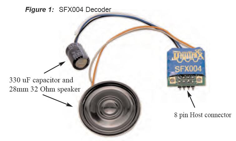
4) Mount the attached 28mm speaker in an appropriate sound enclosure.
Be sure to inspect the speaker diaphragm for magnetic debris or damage, which will affect sound quality.
Other speakers may be substituted in combinations as long as the total impedance on the Orange/Gray wires is 8 ohms or greater.
5) Mount the 330uF/25V electrolytic energy-storage capacitor.
It is often easiest to use double-sided tape to locate and secure this capacitor.
Be sure not to short the capacitor case or leads to the track leads or locomotive frame, or damage to the decoder may result.
6) For Steam units with a synchronization cam capability, connect the White CAM lead to the cam output connection, and program CV133 to 128 for external CAM operation.
7) Inspect the installation before testing the sounds and replacing the shell.
Take extra care to inspect that the SFX/SoundBug is clear of any moving parts such as e.g. flywheels in many of the possible locomotive installations.
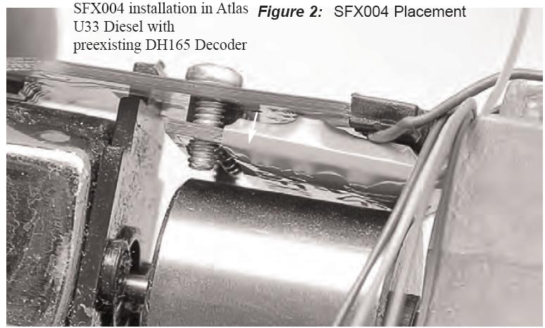
In most older units tested, using the DH165A0 and SFX004 combination, there is typically 1 to 2mm of flywheel clearance, if the Soundbug is correctly mounted flush and parallel to the host DH165 decoder.
Space up or shim the DH165 series decoder to ensure an adequate separation with no binding.
8) Connect DCC track power from a compatible DCC system and select the factory default address 03 to enable SFX sounds for testing.
9) Be sure F8 is OFF, and then press F1(bell) or F2 (whistle/horn) ON to hear these associated sounds.
10) Customize sounds by programming Sound CV's to adjust the desired configurations, as shown in the tables of Sound FX CVs.
Sound schemes other than the default Steam (CV60=0) or Diesel (CV60=1) schemes may be loaded by using a Digitrax PR3 Sound FX Programmer.
Note:
For standalone operation without a DH165 series host decoder, DCC track power may be connected to the two gold ringed pads with holes that the two 2/56 screws engage on the Soundbug.
Do not short or connect to any other of the 8 pin connector pins.