Product Support for: Accessories -> Tester Modules (2 pack) (LT5)
View the Product Page for the LT52 Pack LT5 Tester Modules
4 Articles Found for LT5
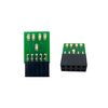
There was an error In the BDL168 Instruction Sheet, Figure 6 on Page 19. The LT5 diagram was incorrect. This article shows the correct LT5 Detection Sections. The current on-line version of the BDL168 Instruction Sheet has been corrected. Each BDL168 comes with an LT5 that will help you with layout wiring and troubleshooting for transponding & detection. The LT5 plugs onto the LED header connections of BDL168 and the LEDs on the LT5 light when detection sections are occupied. The status of power to each zone is also shown. In service, the LT5 is plugged in to one of ...
Q: What are the differences and similarities between the LT5 module that is included as part of the BDL168 package and the Block Monitor module that is included as part of the BD4 package? A: These two devices are for all practical purposes interchangeable. Similarities – They use the same electronic schematic. Differences – They use different leds and different display configurations. The LT5 that comes with BDL168 has 5 red LEDs, four on the top row, and one on the bottom row. The Block Monitor that comes with BD4 has of 5 green LEDs in a single row. Either module can ...
Here are several things to check if you are having trouble with the BDL168: Proper Wiring Be sure that you have NOT connected pin 11 to pin M, as this can prevent proper LocoNet communication. Check to make sure not wires are touching adjacent pins. Follow the wiring diagram closely. Packet Reception Be sure the green ID LED is ON & is “winking” off about every 2 seconds. This means that correctly formatted DCC packets are being decoded from the left most (Railsync) pin of the RJ12 LocoNet socket. For DCC detection, the same DCC packet signal that drives the ...
Testing the installed TF4 for correct transponder operation1. Place the unit with the installed TF4 on an empty transponding track section. This test assumes that the transponding track section is already set up, tested and is working before you start TF4 testing.2. Using a DCC throttle, select the TF4 address that was programmed into the TF4 and verify that the transponder detector identifies the presence of the transponder device. Depending on how you have set up your transponding reporting to the system, your system should detect the presence of the address in that transponding section.For example, if you have an ...