This article courtesy of Ross Webster, which dates from an earlier era before Bachmann made accommodations for DCC installs:
There may be others ways do to this conversion, but this is the way I found using the Digitrax DG380 (any DG wired decoder can be used for this installation)
DUE TO SOME OF THE FRAGILE ITEMS ON THE SHAY I WORKED ON A FOAM PAD SO THERE WAS NO DAMAGE TO ANY OF THE SMALL PARTS.
I first tested the electrical items and made the following determinations.
Free running for the two trucks was .8 amps, total. Stall, was 4.6 amps total for both trucks. Smoke current was 220 ma. All lights were 6 volts and drew .057 ma each.
Tender
Remove the tender cover as per the instructions and the precautions (re weight). I will be using the tender to install the PH sound system. I remove the rear small board making a note of the chuff connection and the rear truck wires. I cut the wire to the rear light and added a plug connection so I could remove the tender cover to complete my work and so I could plug it back in when completed. I added a black wire to each truck feed so I can supply track power to the battery charger for the PH board, as I was not planning to use the batteries and then joined them back together.
Trucks
Remove the cover from the trucks, (the ones you take off to lube it). After they are off there are two more screws on the outside of the housing, one on each side of the truck that attaches to the swivel bracket on the top. When both of these screws are out, the truck will come off. You will see two blue wires attached to the motor and the other end is attached to the pick up bar on the bottom. Disconnect them from the pick-up bar either by cutting or unsoldering. IF YOU PULL OUT THE PICK-UP BARS, BECAREFUL NOT TO LOOSE THE SMALL BALL BEARINGS THAT RIDE AGAINST THE WHEELS TO PICK-UP POWER. Pull the blue wires to the top. That completes the truck power separation.
Stack & Dome
I removed the smokestack and dome closest to the stack for accessibility. These both just pull out. The next dome does not need to come out.
Boiler Front (Smoke Box)
I removed the front cover to get at the smoke unit. The cover just pry’s off and the smoke unit requires the removal of two screws. This step may not be necessary as I removed it to facilitate the threading of wires to the ash pan. You may also consider replacing the smoke unit, but I used the original one as it was still working.
Ash Pan
Remove the two screws holding the ash pan on. The circuit board comes out with the ash pan. Remove one small screw in the center and the board comes away from the ash pan.
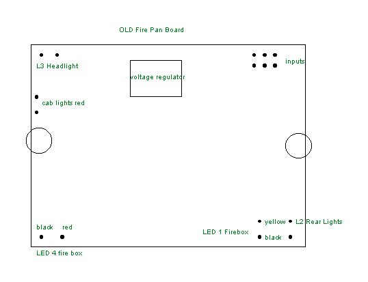
Since the decoder has a built in flicker circuit I decided to remove the board. Before I did this I identified all the wires on the board. Fig 1 below shows the position of all the wires removed. Note there are 2 inputs from the front truck and two inputs from the rear truck and the other two inputs are from the smoke unit and these should be identified and tagged. You will also need to identify which is left and right wires for the truck pick-ups for later reconnection. I threaded a gray and orange #22 wires from the front truck through the boiler and into the ash pan. I used a fine brass wire to get it through. I then threaded a pair of gray and orange #22 wires to the rear through the plastic conduit, which ends in the ash pan. I actually started at the ash pan end. I also added two more small wires through the tube to control the bell & horn on the sound system. Before I fed it through the speaker grill to the tender I spliced in a gray and orange feeder to later go to the sound system. I removed both swivel truck tops and fed the gray and orange wire down through where the black rail pick-ups already go. I took a small round file and just cleaned the slots, where the black wires go through before putting the orange and gray wire through.(one in each slot)
THIS FOLLOWING STEP IS ACTUALLY DONE LAST ALTHOUGH I HAVE DESCRIBED IT HERE FOR CLARITY. I LEFT IT TILL LAST DUE TO THE WEIGHT OF THE TRUCKS AND I STILL HAD A LOT OF OTHER ITEMS TO DO. You need to connect the orange wire to the positive side of the motor and the gray to the negative side. I soldered the wires on and used shrink rap, but a plug would have also worked. The truck goes back together in reverse, and you may consider lubing it before you assemble as while you can clearly see all the parts. Make sure all the wires fit in without binding. 
FIG 1
Ash Pan Continued
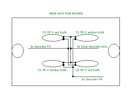
I made up a board from a circuit board material, the same size as the electronic board as per Fig 2. I added four 12-16 volt bulbs to the board and split the circuit so they could be driven by two different decoder functions. 
FIG 2
Since the circuit was decoder driven, it is independent of the speed of the Shay and it can
sit and flicker or be shut off.
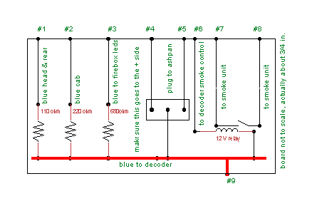
FIG 3
Fig 3 was made as a connection board. The above one is not to scale and it fits on the inside of the firebox. It is about ¾ in high and just under the inside length. It fits in with double-sided tape after the wiring is complete. Make sure it is positioned high enough to allow the firebox cover with the "flicker board" to go back on. The decoder fits on the other side with double-sided tape after the wiring is done. The plug attaches the ash pan lights to the board.
|
# |
Description |
|
|
1 |
Goes to the blue return for the front and rear headlights. The other wire from the lights goes to the decoder. |
|
|
2 |
Goes to the blue return for the cab lights. The other wire from the lights goes to the decoder. |
|
|
3 |
Goes to the blue return for the firebox leds. Make sure it is the positive side. The other side of the led goes to #4& #5 |
|
|
4 |
Goes to FX decoder wire and the fire box led joins here |
Note 1 |
|
5 |
Goes to FX decoder wire and the fire box led joins here |
Note 1 |
|
6 |
Goes to decoder smoke control |
Note 2 |
|
7 |
Goes to one of the track wire. (the other smoke wire goes to the other track lead) |
Note 3 |
|
8 |
Goes to the smoke unit |
Note 3 |
|
9 |
Goes to decoder blue lead |
|
Note 1 I now believe both firebox LED’s and the ash pan lights could be fed from one FX decoder wire without a noticeable difference in the flickering firebox effect.
Note 2. There should be a diode across this coil as per the decoder manual.
Note 3. The smoke unit is fed by the black wires from the trucks which are the left and right rail and are connected together in the ash pan. One of the wires is cut and connected to 7 & 8.
I have not described the sound hook up as they are different for the various makes, except if you are putting it in the tender you will need the bell and light control wire in the conduit.
Caution: The decoder manual should be followed in all cases and each circuit should be tested as it is completed.