We recommend testing your new SE8C prior to installation on your layout.
The following testing procedures will help familiarize you with the general operation of the SE8C.
Track power needs to be ON, a working LocoNet connection and a throttle or PC running DCC control software.
Pre-Installation Set-Up
1. Solder one wire from a 12V AC or 15V DC power supply to Pin 3 and the second wire from the power supply to the Pin C on the 44-Pin edge connector; this powers the SE8C. Digitrax manufactures the PS14, which is appropriate for this installation. Multiple SE8Cs can be powered by a single shared power supply as long as you provide at least 100mA for each SE8C. This power supply should not power any devices other than SE8C and BDL16 series detectors.
2. Connect a working LocoNet to either LocoNet Jack on the SE8C using a LocoNet cable. These jacks bridge through LocoNet so you can daisy chain from one LocoNet device to the next. Your working LocoNet can be from either a PC running DCC control software or a LocoNet command station and throttle.
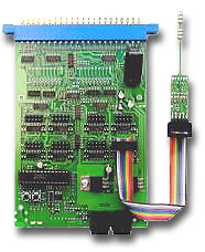
3. The SE8C is shipped from the factory with the Test Mast and Test Signal Driver Cable. One signal driver cable connector should be plugged into the SE8C board so that the brown wire (Pin 1) is to the right (Figure 1), closest to the edge of the board. The test mast should be plugged into the other connector on the cable so the face of the mast is toward you and the brown wire is on the left. This is called the “A” orientation.
Note: There is a small arrowhead on the Signal Driver Cable connectors over the brown wire that points to Pin 1 of the cable. Pin 1 of the Signal Mast is indicated by the square pad on the bottom left Pin on the front of the mast.
4. Power up SE8C. The green ID LED will light up. The red Option LED will blink when a LocoNet message is seen. The red LEDs on the test mast will light.
5. Before testing, be sure the SE8C is set to factory settings. If settings have been changed, reset the SE8C to its factory settings. (Please see related article, below)
Pre-Installation Testing - “A” Orientation Signals
Your SE8C has 8 Driver Sockets (DRV1-DRV8).
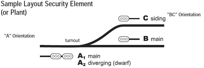
You can plug a Signal Driver Cable into each SE8C Driver Socket to control as many as four signal heads per Driver Socket, each with 4 lighting aspects, enough to control the signal elements for a single security element (or plant) as illustrated below.
Whether the signal driver operates as the A1/A2 or as the B/C signals is determined by the orientation in which the Signal Mast Base is plugged in to the sub-road bed base.
6. To test the operation of the top signal (A1 - Main) of the test mast, select Switch 257 using a throttle or PC control program. Close the switch, the top signal should change to green. Throw the switch and the signal should change back to red. Toggle between red and green aspects by throwing and closing Sw257. Next, select Sw258 and close the switch. The top signal should change to flashing yellow. Throw Sw258 and the signal changes to steady yellow. The last switch command sent to the signal overrides the previous command and is remembered by the SE8C until changed.
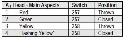
[*] Flashing Yellow aspect can be changed with OpSw settings.
See SE8C Option Switch Settings.
7. To test the operation of the lower signal (A2 - Diverging/Dwarf) of the test mast, select Sw259 using a throttle or PC control program.
Close the switch, the lower signal should change to green.
Throw the switch and the signal should change back to red.
Toggle between red and green aspects by throwing and closing Sw259.
Next, select Sw260 and close the switch.
The lower signal should change to flashing yellow.
Throw Sw260 and the signal changes to a steady yellow.
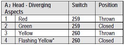
[*] Flashing Yellow aspect can be changed with OpSw settings.
See SE8C Option Switch Settings.
Pre-Installation Testing - “B/C” Orientation Signals
8. Unplug the Test Signal Mast, turn it around so that it faces the opposite direction relative to the Signal Driver Cable. Pin 1 of the Test Signal Mast will be plugged into the socket over the black wire of the Signal Driver Cable. This is called “B/C” Orientation.
9. To test the operation of the lower signal (B-Main) of the Test Mast, first select Sw261 using a throttle or PC train control program. Close the switch, the lower signal should change to green. Throw the switch and the signal should change back to red. Toggle between red and green aspects by throwing and closing Sw261. Now select Sw262 and close the switch. The lower signal should change to flashing yellow. Throw Sw262 and the signal changes to a steady yellow.
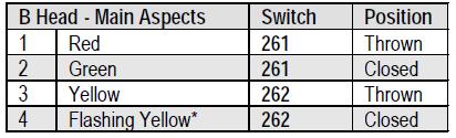
[*] Flashing Yellow aspect can be changed with OpSw settings.
See SE8C Option Switch Settings.
10. To test the operation of the upper signal (C-siding) of the test mast, first select Sw263 using a throttle or PC control program. Close the switch, the lower signal should change to green. Throw the switch and the signal should change back to red. Toggle between red and green aspects by throwing and closing Sw263. Now select Sw264 and close the switch. The should change to flashing yellow. Throw Sw264 and the signal changes to a steady yellow.
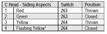
[*] Flashing Yellow aspect can be changed with OpSw settings.
See SE8C Option Switch Settings.
11. Test the other SE8C Driver Sockets to verify the aspects show properly and there are no cable or connector problems. The factory-default settings for controlling aspects are listed in the related article.