There was an error In the BDL168 Instruction Sheet, Figure 6 on Page 19. The LT5 diagram was incorrect. This article shows the correct LT5 Detection Sections. The current on-line version of the BDL168 Instruction Sheet has been corrected.
Each BDL168 comes with an LT5 that will help you with layout wiring and troubleshooting for transponding & detection. The LT5 plugs onto the LED header connections of BDL168 and the LEDs on the LT5 light when detection sections are occupied. The status of power to each zone is also shown.
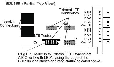
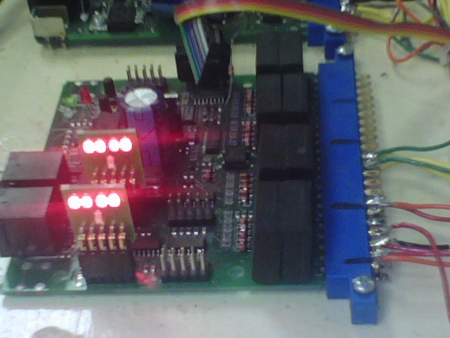
In service, the LT5 is plugged in to one of the 4 LED headers on the BDL168 board. The LED's on the LT5 are illuminated when a train occupies an individual block. A fifth LED shows Power Status for each zone. Here, a BDL168 with two LT5's connected:
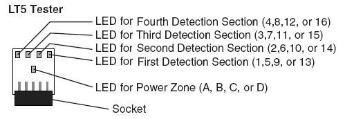
LT5 Tester Diagram