How do I connect a BD4 to a DS64? The BD4 is a block occupancy detection device designed as an add-on device that can take advantage of the LocoNet hosting capability of the DS64 stationary decoder. It is connected in this way:
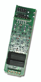
The installation of a BD4 is relatively simple. Looking at the BD4, you will find a 5-point terminal block on one end and two (LED1 and DS1) 10-pin (5x2) headers on the other.
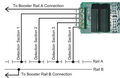
There are three termination areas: a) The 5-point terminal block (left) is for the interconnection between the rail power source and the rails. b) The LED1 10-pin header is for testing the status of power to the rails and block occupancy with the assistance of the supplemental Led indicator panel. c) The DS1 10-pin header provides the interface circuitry for the interconnection between the BD4 and the DS64. The following drawing represents the basic layout and location for rail power, indicator, and interface connections:

Pin 2, or 4, or 6, or 8, or 10 of the DS1 header is the ground wire of the BD4 and needs to be connected to the AX1 terminal on the DS64.
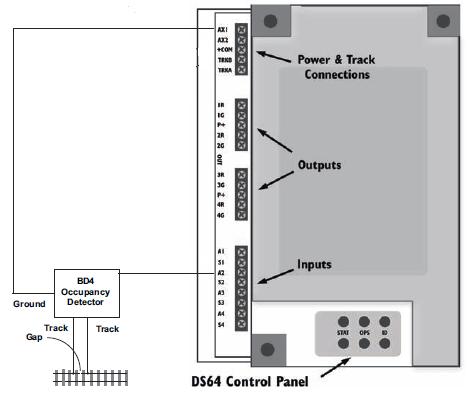
Pins 1, 3, 5 and 7 of the DS1 are the respective outputs for Track Detection Sections 1, 2, 3, and 4. The BD4 outputs can be used in any combination to the DS64 A1, A2, A3 or A4 inputs ("Ax" on the diagram).