Common Rail Wiring
Many older model railroads use Common Rail wiring because they were initially wired to operate with electrical toggle switches.
Conversion to DCC is possible with Common Rail, but it is not recommended.
Whole layout common rail is a method of wiring layouts where power districts and their boosters are electrically connected using a common rail or common power bus return wire.
Whole layout common rail wiring is a disadvantage when it comes to detection systems since detectors cannot independently monitor whether zone power is on or off so they can't tell whether occupancy detection is working in any given detection section.
See Figure below for an example of Whole Layout Common Rail Wiring wiring with a single power district and one zone with four detection sections.
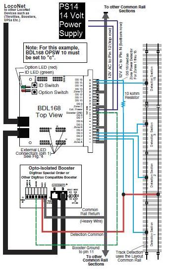
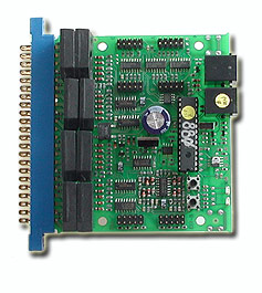
Wiring the BDL168 for Whole Layout Common Rail Wiring
Whole layout common rail wiring cannot independently monitor whether zone power is on or off so it can't tell whether occupancy detection is working or not in any given detection section.
The BDL168 can be easily configured to overcome this disadvantage by using detection section 16 to monitor track power--if track power is on in section 16 then detection is working in sections 1-15.
1. After mounting the 44-pin connector to the board (see related articles), label the connector Using the zones and detection section numbers for easy identification of the pins when wiring.
2. Solder one wire (AC1) from a 12-16V AC or DC power supply to the pin 12 and the second wire (AC2) from the power supply to the pin N on the BDL168's 44-pin connector. This powers the BDL168. Multiple BDL168 units can be supplied by a single shared supply as long as you provide at least 100mA for each BDL168. This power supply should not power any devices other than BDL168s.
3. Solder the ground wire from the Digitrax booster ground or common (case) to pin 11 of the 44-pin connector. Nothing is connected to pin M.
4. The end of the wire from each detection section and zone common should be stripped approximately 1/4