Troubleshooting in General:
Regardless of the guides, manuals, tips, suggestions, experts or whatever, troubleshooting can occasionally degenerate into a vast chasm of darkness and confusion. It would be impossible to cover all the areas that have, can or may cause problems. This is a general guide to identifying and resolving problems with Digitrax Complete Train Control.
Keep Good Records:
Although it may seem to be a pain while setting up your Digitrax system, keeping layout records can be very helpful, even with the simplest of railroads.
- You should have a plan and a wiring diagram of the layout.
- You will also need a log for the locomotives which should include the decoder installed, with addresses, any special programming and other information about the locomotive. Fortunately, programs like Decoder Pro and Train Programmer make this process easier.
- You will also need a similar log for any devices that require programming or special configurations such as the DS64, BDL168, SE8C and others. Digitrax recommends keeping a record of device settings (such as addresses, Block ID and the like) to make troubleshooting easier.
Read the Manual:
Yes, we know what you're thinking, but the manufacturers spared no expense to write manuals so it would help to at least know where you put them. If you can't locate the paper copy, you can always download the PDF version from our website.
Identify the Problem:
- The first and foremost rule of trouble shooting is "WHAT happened?" or "What changed just before the problem struck?" Once the guilty have been identified and punished then one can move on to solving the problem.
You must be systematic:
You can never have enough information to use in trouble shooting:
- What is wrong? Describe what is actually happening on the layout and what you think should be happening.
- When did it happen? It's always best to troubleshoot an issue as soon as you observe it.
- Where did it happen? Is the problem related to a certain area of the layout? Can you recreate the problem on your test track?
- What was the last change made to the layout?
- In a group environment, you might want to know who found the problem?
- Who worked on it last?
- Do you need to call tech support?
- And so on!
The system manuals and the Tech Support Depot have glossaries that will help with understanding the terms and equipment of DCC.
Troubleshooting Tools:
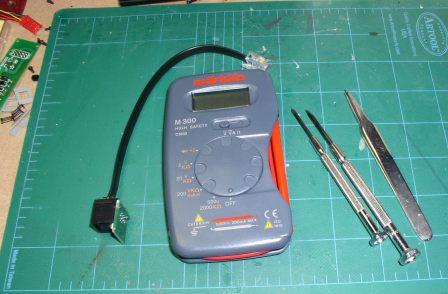
There are basic items, tools, which you will need for trouble shooting. - First: A good VOM (volt, ohm, milliamp meter), also called a multimeter, is indispensable in measuring voltage and resistance. Most any of the inexpensive meters will do.
- Second: A United States 25 cent piece, or similar size coin, sometimes called a quarter. Hence, this is called the quarter test.
- Third: The manuals mentioned above.
- Fourth: Patience.
- Fifth: Small hand tools, the same ones that you used to get yourself in this predicament in the first place.
- Sixth: An LT1 LocoNet Tester, which is included with all Digitrax starter sets.
There are several major categories of DCC system problems:
- Track Problems
- Command Station / Booster Problems
- LocoNet Problems
- Throttle Problems
- Radio Problems
- Status Editing Issues
Track Problems
- The most common problem on the layout that will impact your DCC system are electrical short circuits. If you find that you cannot get Track Status to come up and the number of beeps from the booster were lost in the general confusion, then disconnect one of the Rails from the booster and the problem should be apparent.
- The quarter test is the BEST diagnostic tool that you have! With the DCC system up, with Track Status ON, using a quarter, short the layout every six feet or so and the booster should shut down and beep.
- If the booster does not beep and shut down, then you have a wiring problem that must be addressed. Your system manual covers this in the Track Wiring Considerations section.
- Gaps, as in rail gaps, are NOT permanent! They will close up, due to temperature and humidity changes, and cause all kinds of misery.
- Locomotives and cars sitting on turnouts and gaps have caused more gray hair than kids.
- Phase mismatches between power districts are usually cleared by swapping Rail A with Rail B on one of the boosters.
- Track, turnouts, crossovers, wheel sets, etc., must be checked with a Standard gauge. The NMRA has a gauge for each scale.
- A quick way to identify track problems is to run an analog locomotive around the layout. Any problem that the locomotive has is most likely caused by the track.
Command Station / Booster Issues
Command Station / Booster Issues - Input voltage:
- The input voltage to the Command Station / Booster can be either AC or DC. The booster has a full wave filtered bridge inside to handle the AC or DC with ripples.
- Both the system manual and the Caution label on the bottom of the booster indicate the proper voltage/current requirements.
- Measure the input voltage at the Power In terminals on the booster. To measure the system current draw place an ammeter of the proper rating in series with one of the leads from the power transformer to the booster.
- Basic input voltage is 12 to 24 volts. The current input will vary depending upon the system; typically, this is 5 amps, but may be lower or higher depending upon the system. In the case of Zephyr, the unit will not handle more than 2.5 amps, so having a 5 amp supply will still result in only 2.5 amps output. On the other hand, using a 2.5 amp power supply with a 5 amp command station will result in only 2.5 amps output even though the unit is rated at 5 amps.
- Low input voltage (and/or low current ) will result in unpredictable locomotive performance and should be one of the first areas checked if using a power pack from a DC layout.
Command Station / Booster Issues - Output voltage:
Track voltage (output from the booster to the rail ) is measured as follows:
- With the system on and with Track Status on, select the analog address,00, and set to speed 00.
- With a multimeter set to the 20 volt DC scale measure from Rail A to ground ( the toggle switches on the booster are grounded ), then from Rail B to ground.
- With the command station's SCALE switch set to N-scale the readings should be about 6.2 volts DC, for each rail. Total track voltage is the sum of the two, or about 12.4 volts DC. At the H0-setting the rail voltage should be 7.5 volts DC each. At the G/O setting it should be 10 volts DC each.
The difference between the rail voltages should not exceed 0.2 volts. Satisfactory operation will still occur if the difference is as much as 0.5 volts DC.
Adjusting Track Voltage:
Track voltage may be adjusted using the yellow trim pot inside the booster located between the LocoNet B port and the Scale switch. This can used to balance the track voltage between booster power districts.
Note: With the DCS100, DCS200 and DCS50, the Programming Track (identified as PROG A and PROG B) is NOT powered. You cannot run locomotives on the program track. After programming, transfer the locomotive back to the layout to run.
Command Station / Booster Problems:
In general, trouble shooting with the Command Station / Booster begins with the indicator LED's and the beeps. Get familiar with what the various indicator LED's represent and what the series of diagnostic beeps means. For example, a soft ticking from a DB100 is an indication that the DB100 is no longer talking to a command station. Please see related articles, below.
Command Station / Booster Problem - Short Circuits at the rail:
The booster will react to a rail short by beeping and shutting down, Track Status indicator will go OFF. When the short clears the booster will beep and Track Status will come ON. IF the booster can NOT “see” the short it will not shut down but will pump current into the problem until something smokes.
The Quarter test is essential in testing track wiring such that no matter where the short occurs the booster will “see” it and shut down.
Command Station / Booster Problem - Other Short Circuits
A short circuit on LocoNet will bring down the network and the system will cease to run trains. The LT1 can be used to test for LocoNet problems both in the cables and in the LocoNet devices.
A booster internal short circuit may cause the Track Status LED indicator to go solid Red or Green and may also trip the power supply circuit breaker or fuse.
Command Station / Booster Problems - Incorrect OpSw Settings
The Option Switches, (OpSw's), allow the booster to be configured to suit individual layout parameters. However, the OpSw's can also be incorrectly set to disable the booster, which can lead to much hair pulling. The OpSw's usually get set incorrectly when the system is new and the resident button pusher is at work. The system manual contains a list of the OpSw's, their function and the default settings. Please see related article, below.
For example, if OpSw #01 is closed, the booster and LocoNet go dead. So always check the OpSw's if there is a problem.
Command Station / Booster Problems - Full Registers
When the command station registers fill up, the throttle will show an error display when trying to SELect an address. Other odd symptoms may also show up; at this point, it may make sense to reset the command station / booster. Please see the related articles, below.
LocoNet Problems
LocoNet is the communication network for your Digitrax system; trouble on LocoNet means trouble on the entire system. Because of its design, LocoNet is very robust and will tolerate a lot of problems. Even so, it is very important that trouble be identified and resolved.
LocoNet Problems - Using the LT1:
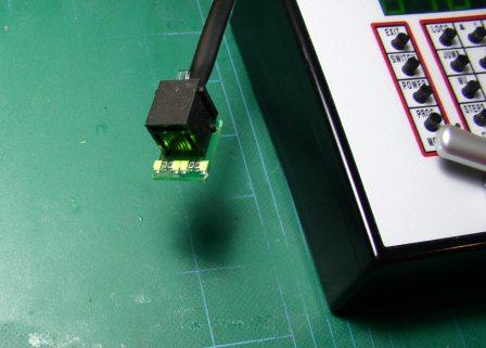
The LT1 is furnished with each starter set to allow testing of LocoNet cables and the LocoNet devices, such as the UP5. When testing with the LT1 remember that a throttle has to be plugged into LocoNet for all four of the LED's on the LT1 to light. When a LocoNet device or cable is "good", the LT1 will show all four of the LED's at the same brightness.
A short LocoNet cable, two to three inches, with one of the plugs reversed is handy to have for testing devices with the LT1.
LocoNet Problems - LocoNet Voltages:
1. White, LocoNet Signal, 5 – 7 VDC
2. Black, Ground
3. Red, LocoNet Power, 10 – 15 VDC
4. Green, LocoNet Power, 10 – 15 VDC
5. Yellow, Ground
6. Blue, LocoNet Signal, 5 – 7 VDC
LocoNet Problems - LocoNet Devices:
The Universal Panels, UP5, UR90, and the UR92 & UR91 are fascia mounted LocoNet devices for the connection of throttles. The LocoNet ports on the front of these devices are intended for throttles only, while the ports on the back are for linking LocoNet to other devices. They are DIFFERENT from the front ports! So use the front ports for throttles only.
LocoNet Problems - Other:
A not so common problem can occur when one of the pins in the LocoNet port is crossed over another. Look inside each port to be sure that the pins are lined up in their respective slots.
Throttles
The throttle is the primary input device for the DCC system. Each throttle plugs into LocoNet, which permits it to communicate with all the devices active on LocoNet. The throttles have multiple configuration options that can be set by the user. For details, please see the appropriate section in the system manual that talks about Configuration Options.
The DT-Series and UT-Series throttles, when initially plugged into an active LocoNet, have a “wake up” period that can last as long as 16, or more, seconds.
Throttle Problems:
If the display shows IDLE:
- The throttle has a good battery and/or is not connected to an active LocoNet. Or,
- The LocoNet is Off Line; the booster may have been switched to SLEEP.
Does the throttle beep and LCD light up when a battery is first installed?
- No: Is the battery dead?
- The CPU may be out of its socket. See notes at Illegible characters or blank display below.
- One of the wires from the PCB to the case may be broken.
Illegible characters or blank display:
- The CPU may be out of its socket. It can usually be reseated by tapping the back of the throttle against the palm of your hand. If this does not work, you'll need to send it in for repair. Opening the throttle case should not be done by end users to avoid doing damage to other components.
Skipping or erratic numbers while turning a knob:
- Bad encoder. Encoders for all current production units can be replaced. Some older throttles can no longer be repaired so, check the repair section of our website to make sure before you send an older throttle in for repair.
Does the throttle beep and display light up when plugged into LocoNet without a battery?
- No: Bad connector or port. Check to see that the connectors inside the socket are not misaligned. Replace the connector on your throttle using a good quality crimping tool and new connector.
- There may be internal problems.
- LocoNet trouble.
Radio Problems:
The DT400D and UT4D are duplex radio throttles. DT400R and UT4R are simplex radio throttles. The DT400 and UT4 include infrared transmitters.
The UR92 is a combination duplex radio transceiver and infrared receiver. The UR91 is a combination simplex radio and infrared receiver. The UR90 is an infrared receiver only.
A typical duplex radio problem is that the locomotive does not respond to commands. Make sure the throttle is configured to run as a duplex throttle. Make sure the throttle and UR921 transceiver both have the lastest software update installed.
A typical simplex radio problem is that the locomotive does not respond when the radio throttle is tetherless. This can be either a throttle problem or a receiver problem. Plug the throttle into the UR91 and try again. Be sure that the throttle is configured for radio operation.
Most infrared problems are caused by the throttle not being able to "see" the reciever. Install your UR90s above head height. You may need to add more UR90s to get enough coverage.
Please see the related articles about optimum performance for UR90, UR91, and UR92 below.
Status Editing Issues
Status editing is a command station function that allows you to operate locomotives that are fitted with simpler decoders that do not operate at 128-speed steps. Status codes are assigned by the system to each locomotive address that is active or being Selected. Since most modern decoders are designed to operate at 128-speed steps, status editing is rarely used.
IT IS ALMOST NEVER NECESSARY TO CHANGE THE STATUS OF A LOCOMOTIVE ADDRESS!
Please spend at least a moment to look at the Status Editing section in your system manual. Also, note that Status Editing has NOTHING to do with Programming .
Locomotive Decoder Problems:
In addition to the tools described here, please see the related article "Trouble Shooting Mobile Decoder Problems", below.