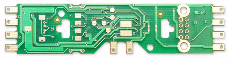
1. Carefully remove the locomotive's shell from the frame.
Notice the orientation of the circuit board inside so that you can install the decoder in the same orientation. (Figure 1)
2. Remove the 10 black plastic plugs from the lightboard that secure the wires to the PCB.
There are 4 plugs (retainers) on each end and 2 on the side for the motor connection.
Remove the red and black wires, carefully noting where each wire originally connected to the PCB.
Remove the lightboard itself by pinching the black plastic release tabs and pulling the board up and off of the loco frame. (Figure 1)
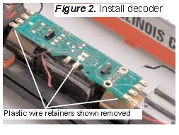
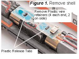
3. The DH165A0 decoder is installed in the same orientation as the factory board.
Push the decoder over the plastic release tabs to hold it in place on the frame.
Reconnect the wires to the decoder in the same configuration as the factory board using the black plug/wire retainers. (Figures 2 and 3)
Installation Notes:
1. Do not exceed the decoder's 500mA total function output rating.
2. To use a function output with an inductive (coil) type load, see the Digitrax Decoder Manual for more information to avoid damage to the decoder.
3. See the Digitrax Decoder Manual for full details of wiring 12-16V lamps, 1.5V lamps, and LEDs.
Lamps that draw more than 80 mA when running require a 22 ohm 1/4 watt resistor in series with the directional light function lead to protect the decoder.
4. Some locomotives employ filter capacitors for RFI suppression in the locomotive wiring.
These may cause problems with Supersonic decoders and non-decoder analog operation on DCC.
This capacitor should be removed for safe operation.