Q: What is the basic configuration and OpSw settings for a section of the PM42 when configured for circuit breaker control?
A: The PM42 is a 4 section multi-purpose device where each of the four sections can be individually configured to act as either a circuit breaker, or automatic reverse loop controller.
The PM42 monitors the current flow to the rails and interrupts the connection when it senses that the current demands exceed the upper allowable current level determined by the User controllable Option Switch (OpSw) settings.
The power flow of a layout's command control system starts with the command station, or booster, then passes through power management devices (circuit breakers, reverse loop controllers, and block occupancy detector), finally terminating at the rails.
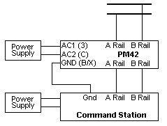
The following diagram indicates the minimum configuration for a section of the PM42 when configured for Circuit Breaker Control.

The connection of the PM42, when configured to perform the task of a circuit breaker is simple.
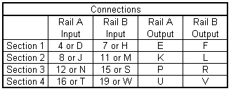
The following chart identifies the pins (for both input and output terminals) of the 44-pin edge connector.

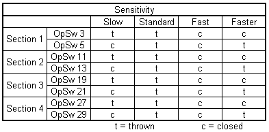
The sensitivity of the PM42, when configured to program the task of circuit breaker is simple.
All four sections can be programmed for with the same settings for each section of the PM42 or each section can be programmed separately as necessary.
The factory default sensitivity is “Standard”.
The following chart identifies the Op Switch (OpSw) settings available for the PM42.

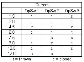
The trip current setting of the PM42, when configured to program the task of circuit breaker is simple.
All four sections can be programmed for with the same settings for each section of the PM42 or each section can be programmed separately as necessary.
The factory default sensitivity is 3 amps.
The following chart identifies the Op Switch (OpSw) settings available for the PM42.

Note 1: The trip current setting must be reduced to a lower setting when the PM42 is used with the Digitrax Zephyr (DCS50) or any other third party booster where the maximum output is less than 3 amps.
Note 2: The PM42, as shipped from the factory, can be used in conjunction with most DCC command system currently available.
Note 3: The preferred configuration for programming the PM42 is by using a Digitrax DT series, or equivalent, throttle in conjunction with an active LocoNet.
The PM42 can also be programmed by the installation of a program jumper on the PM42 circuit board and a powered Digitrax DT throttle.