How do I set up the SE8C to control semaphores?
Installing Semaphore Type Signals with SE8C
The SE8C can be set up to use its 8 turnout motor drive outputs to run 8 three-position semaphore (arm type) signals using slow motion turnout control machines (such as the TortoiseTM machines) as actuators. These 8 semaphore signals are available in addition to the standard 32 LED signal heads on the 8 signal control cables and occupy a separate semaphore address control range.
The SE8C automatically sequences the three possible mechanical arm positions to match 3 aspects of red, green and yellow using a position sense feedback wire from the slow motion turnout machine’s auxiliary contacts.
Enable Semaphore Operation
To enable semaphore operation, you must set Option Switch 11 to closed and set the semaphore switch control range you want to use for the semaphores as follows:
1. Wire the 44 pin edge connector to the slow motion turnout machines using 3 wires per semaphore and a positive common wire as shown in one of the following diagrams.
2. Power up the SE8C and connect it to LocoNet.
3. Wire the semaphore lamp via an appropriate brightness setting resistor to a separate power supply per the signal manufacturer’s instructions.
4. Press the Option Switch on the SE8C Board until the red LED blinks, then release. The red and green LEDS will blink alternately to indicate that you are in Option Switch Mode. Switch commands issued while in OpSw mode will change the factory settings of the SE8C.
5. Using your throttle or PC, set OpSw11 to c (closed) to put the SE8C into semaphore mode.
6. To set the semaphore address control range to be used for the semaphore, set OpSw19 to c (closed). The next switch command you send will set the range of 16 semaphore control addresses that will be used to control the eight semaphore signals connected to your SE8C. For example, if you set SW65=c, the range of addresses used for the operation of the semaphore turnout machines will be Sw65-Sw80.
|
Semaphore Control Switch AddressRange 16 Per SE8C |
Broadcast Control Switch Address Range 2 Per SE8C |
|
SW01-Sw16 |
Sw01-Sw02 |
|
Sw17-Sw32 |
Sw09-Sw10 |
|
Sw33-Sw48 |
Sw17-Sw18 |
|
Sw49-Sw64 |
Sw25-Sw26 |
|
Sw65-Sw80 |
Sw33-Sw34 |
|
Sw81-Sw96 |
Sw41-Sw42 |
|
Sw97-Sw112 |
Sw49-Sw50 |
|
Sw113-Sw128 |
Sw57-Sw58 |
|
Sw129-Sw144 |
Sw65-Sw66 |
|
Sw145-Sw160 |
Sw73-Sw74 |
|
Sw161-Sw176 |
Sw81-Sw82 |
|
Sw177-Sw192 |
Sw89-Sw90 |
|
Sw193-Sw208 |
Sw97-Sw98 |
|
Sw209-Sw224 |
Sw105-Sw106 |
|
Sw225-Sw240 |
Sw113-Sw114 |
|
Sw241-Sw256 |
Sw121-Sw122 |
|
Sw257-Sw272 |
Sw129-Sw130 |
|
Sw273-Sw288 |
Sw137-Sw138 |
|
Sw289-Sw304 |
Sw145-Sw146 |
|
Sw305-Sw320 |
Sw153-Sw154 |
|
Sw321-Sw336 |
Sw161-Sw162 |
|
Sw337-Sw352 |
Sw169-Sw170 |
|
Sw353-Sw368 |
Sw177-Sw178 |
|
Sw369-Sw384 |
Sw185-Sw186 |
|
Sw385-Sw400 |
Sw193-Sw194 |
|
Sw401-Sw416 |
Sw201-Sw202 |
|
Sw417-Sw432 |
Sw209-Sw210 |
|
Sw433-Sw448 |
Sw217-Sw218 |
|
Sw449-Sw464 |
Sw225-Sw226 |
|
Sw465-Sw480 |
Sw233-Sw234 |
|
Sw481-Sw496 |
Sw241-Sw242 |
|
Sw497-Sw512 |
Sw249-Sw250 |
|
Sw513-Sw528 |
Sw257-Sw258 |
|
Sw529-Sw544 |
Sw265-Sw266 |
|
Sw545-Sw560 |
Sw276-Sw274 |
|
Sw561-Sw576 |
Sw281-Sw282 |
7. Exit OpSw mode by pressing the Option Switch then releasing with the alternating LED flashing stops.
8. Check operation of the slow motion turnout machine controlled semaphores. Each semaphore should move to the green position when you set its first semaphore control address to c (closed) and to the red position it is set to t (thrown). It should move to the yellow position when the second semaphore control address is set to either t or c. For example, if you set the semaphore control address range to Sw65-Sw80, the first semaphore will move to the red position when Sw65=c and to the green position when Sw65=t. It will move to the yellow position when Sw66=either c or t.
9. Connect the mechanical linkages from the semaphore signal (such as Tomar H-853) to the slow motion turnout machine that will control the operation of the signal. Set up the linkage throw distance and center (yellow) position to correctly drive the signal without overdriving the unit. In the case of the Tomar H-853, the control range for the actuator is only about 6mm so, you should use a bell crank lever or TortoiseTM remote cable kit with the matching throw ranges to connect the semaphore mechanism.
Standard Tortoise Motor Hook Up Example for Semaphore Operation:
Tortoise turnout machines are a product of Circuitron, Inc., they are used here as an example only. Slow motion turnout motors made by other manufacturers will also work for this application.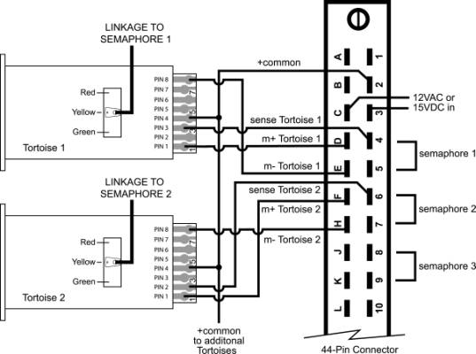
Standard Motor Hook Up from Tortoise to 44 pin connector to SE8C for Semaphore Operation
|
Pin 1 Motor + |
Pin 3 Sense |
Pin 4 + Common |
Pin 8 Motor - |
|
|
Tortoise 1 |
D |
4 |
2 |
E |
|
Tortoise 2 |
F |
6 |
2 |
H |
|
Tortoise 3 |
J |
8 |
2 |
K |
|
Tortoise 4 |
L |
10 |
2 |
M |
|
Tortoise 5 |
N |
12 |
2 |
P |
|
Tortoise 6 |
R |
14 |
2 |
S |
|
Tortoise 7 |
T |
16 |
2 |
U |
|
Tortoise 8 |
V |
18 |
2 |
W |
Reverse Tortoise Motor Hook Up Example for Semaphore Operation:
Tortoise turnout machines are a product of Circuitron, Inc., they are used here as an example only. Slow motion turnout motors made by other manufacturers will also work for this application.
Notice that the difference from the previous example is that the motor and reporting contacts are reversed in this example.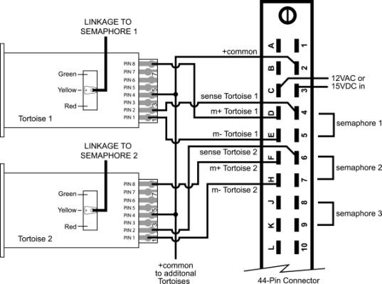
Reverse Motor Hook Up from Tortoise to 44 pin connector to SE8C for Semaphore Operation
|
Pin 1 Motor - |
Pin 2 Sense |
Pin 4 + Common |
Pin 8 Motor + |
|
|
Tortoise 1 |
E |
4 |
2 |
D |
|
Tortoise 2 |
H |
6 |
2 |
F |
|
Tortoise 3 |
K |
8 |
2 |
J |
|
Tortoise 4 |
M |
10 |
2 |
L |
|
Tortoise 5 |
P |
12 |
2 |
N |
|
Tortoise 6 |
S |
14 |
2 |
R |
|
Tortoise 7 |
U |
16 |
2 |
T |
|
Tortoise 8 |
W |
18 |
2 |
V |
Do not connect any wires to the terminals 1,20,22,A,X,Y,Z as these are connected to internal parts of the SE8C.
Troubleshooting semaphore hook up:
1. If there is no response at the expected semaphore address, try the normal switch address for the board ID to see if the slow motion turnout machine output responds (Sw01-Sw08 for Board ID 1). If it responds to this normal switch address command, this means OpSw11 has not been changed to semaphore mode. Repeat steps 4-7 of semaphore set up.
2. If the semaphore can be driven to red and green limits by Sw65 in the test but Sw66=t or c does not drive to the yellow mid-point position, check the wiring to the slow motion turnout machine from the +common line and also the position sense line. If the wiring is not correct, the yellow position cannot be found by the SE8C for the semaphore unit and it will drive to the end limit or may fail to move at all in response to Sw66=t or c.
Note: Be careful when working with the fine wires from the signal heads, they are easily broken.
Note: We strongly recommend that you wire and test the lights prior to installation on your layout.