Product Support for: Detection & Signaling -> Occupancy Detector for 4 detection sections (BD4)
View the Product Page for the BD4When used in conjunction with the DS64 or SE8C the BD4 provides LocoNet detection for 4 occupancy detection sections. BD4 lets you know which detection sections of your layout are occupied by locos and rolling stock.
Not recommended for layouts using "supersonic" decoders unless the "supersonic" feature is turned off in all decoders.
25 Articles Found for BD4
There is an error in the BD4 Instruction Sheet, 2004 version.As a result of this error, BD4 shows no status light and no detection lights. The solution is to connect pin 10 of the DS1 on the BD4 to a system ground such as the AX1 terminal of the DS64, Ground on the booster terminal, etc. This connection was not shown on the original instruction sheet for the BD4.
How do you wire an AR1 with a BD4 so that you get block detection within the reverse loop and without the BD4 permanently detecting the AR1? It should be wired with the AR1 between the power source and the BD4. All four detection sections of the BD4 will have to be inside the reverse loop.
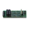
Connecting BD4 to an SE8C?The BD4 is a block occupancy detection device designed as an add-on device that can take advantage of the LocoNet hosting capability of the SE8c signal decoder. It is connected this way: The installation of a BD4 is relatively simple. Looking at the BD4, you will find a 5-point terminal block on one end and two (LED1 and DS1) 10-pin (5x2) headers on the other. There are three termination areas: a) The 5-point terminal block (left) is for the interconnection between the rail power source and the rails. b) The LED1 10-pin header is ...
BD4 Output Each BD4 is situated between the PM42 Power Manager and the railroad. The DCC signal passes from the DCS50 Zephyr, through the Power Manager, through the BD4 to the track to the locomotive. When a locomotive (or equipped car) is present in a track segment, the BD4 also sends out occupancy information, in two ways. Occupancy Information Output LED1 The LED1 10-pin header is for testing the status of power to the rails and block occupancy with the LED indicator which is included with the BD4. The LED1 can also be used for panel indicator lights using LED's. ...
You can automate grade crossing signal lights with block occupancy sensors. Install a BD4 to detect track occupancy as shown in the figure below. Other than removing the Op Sw35 commands from the routes used in the related article example, there is no additional programming needed for the DS64. Sensor operated occupancy detection requires that all rolling stock be equipped with resistor wheels for proper detection or that the detection section is longer on each side of the RR Crossing than the full length of a train since only the locomotive will draw current. A lighted caboose on the end of ...
How do I connect the BD4 to the DS54? The BD4 is a block occupancy detection device designed as an add-on device that can take advantage of the LocoNet hosting capability of the DS54 stationary decoder. It is connected in this way: The installation of a BD4 is relatively simple. Looking at the BD4, you will find a 5-point terminal block on one end and two (LED1 and DS1) 10-pin (5x2) headers on the other. There are three termination areas: a) The 5-point terminal block (left) is for the interconnection between the rail power source and the rails. b) ...
How do I connect a BD4 to a DS64? The BD4 is a block occupancy detection device designed as an add-on device that can take advantage of the LocoNet hosting capability of the DS64 stationary decoder. It is connected in this way: The installation of a BD4 is relatively simple. Looking at the BD4, you will find a 5-point terminal block on one end and two (LED1 and DS1) 10-pin (5x2) headers on the other. There are three termination areas: a) The 5-point terminal block (left) is for the interconnection between the rail power source and the rails. b) The ...
What are the physical dimensions of the BD4 Quad Occupancy Detector? The longest dimension is 3.48 inches. The shortest dimension is 1.03 inches. Height at bridge rectifiers .842 inches and the height with the block monitor installed is 1.062 inches. Remember to allow for wire clearance at the screw terminal end (for the block detection wires) and also allow for vertical clearance for the DS1 and LED1 plug connections at the other end.
Q: What are the differences and similarities between the LT5 module that is included as part of the BDL168 package and the Block Monitor module that is included as part of the BD4 package? A: These two devices are for all practical purposes interchangeable. Similarities – They use the same electronic schematic. Differences – They use different leds and different display configurations. The LT5 that comes with BDL168 has 5 red LEDs, four on the top row, and one on the bottom row. The Block Monitor that comes with BD4 has of 5 green LEDs in a single row. Either module can ...
In this example we add some more features to complete the capabilities of the DS64 / BD4 combination. In addition to the fascia button, we utilize the remaining sensors of the BD4 to automatically select the exit route if triggered by the advancing train. For this purpose, each yard track will need a short detection section just before the yard ladder. A departing train will then trigger and set its own exit route as soon as the engine enters the detection section. To enter the yard however, the routes must still be selected manually with the push buttons.
Q: How can I configure the DS54 for block occupancy detection? A: Any DS54 input can serve as a block occupancy message generator. All that is necessary is to activate a DS54 input with a device that can detect the presence of a train within a specific area/location. The DS54 input can respond to a number of different block occupancy devices including the BD1, BD4, and isolated contacts. The following drawings indicate two different methods (wiring schematics) for the connection of devices to the DS54. The upper drawing Is for isolated contacts and the lower drawing is for BD1 ...
Q: Is it possible to use Digitrax equipment to wire the Kato N-Scale Automatic Track Crossing? If so, how do I do it? A: The answer is a probable "No", but there may be a workaround. The Kato, USA website notes: Some Unitrack components such as the Automatic Crossing Gate and 3-Color Signal were designed with DC operation only. So, the official position is that that these devices don't work in the DCC environment. However, we are not above speculating on how to do this, nor are others. An online web search turned up this bit of message traffic by ...
Q: How do I use the AR1 and automatically control the turnout? I'm confused here. It is good that the AR1 controls the switching of the track power for a reverse loop automatically but it seems the turn out direction also needs auto control. Am I missing something here? Need help understanding...Please explain. A: The AR1 is handles correcting the track polarity mismatch when a reversing section is encountered by a locomotive. When the polarity inside the reverse section does not match the polarity outside the reverse section, the AR1 detects the short circuit and flips the polarity so that ...
Q: How can the DS54 be configured to control a Flashing Crossing Signal? A: The elements necessary to create a simple function flashing/blinking crossing signal are: a block occupancy detection (trigger) device, an electronic flashing/blinking circuit (DS54) and a crossing signal. The DS54 can accommodate two different types of triggering devices: Digitrax block occupancy devices (BD1 and BD4) and third party block occupancy devices (such as magnets and reed contacts). The following drawings indicate how to connect the two different types of triggering devices, along with the crossing signal, to the DS54. The upper drawing is for the BD1 or ...
Q: What is the purpose of the single 6-32 screw terminal beside the input connector? A: The 6-32 screw terminal next to the input connector is the -VE Sensor common for the BD1 and BD4 block occupancy detectors. The 6-32 screw terminal next to the input connector should not be mistaken for the standard system ground. The LocoNet connector handles all of the DS54’s system ground needs. Warning: Do Not Connect the 6-32 screw terminal to a house or earth ground (water pipe, electrical ground connection, earth ground stake, etc.) as it may result in damage to the DS54.
The subject of railroad signaling is a fascinating one. Signals provide a margin of safety and protect the train crews, freight and passengers on the railroad . Grade crossing signals also protect the general public from collision with moving trains. Signal operation relies upon three basic elements: Detection of trains Operation of the signals Operation Logic Signaling is a complicated topic, far beyond the scope of this knowledge base. But Digitrax offers several items which will help you with creating a realistic signal environment. Detection determines the presence or absence of trains. Both the BDL168 and BD4 will ...
Connecting BD1 to a DS54, DS64 and SE8c? The BD1, block occupancy detector (replaced in 2004 by the BD4) was designed as an add-on device, which took advantage of the block occupancy message generating (over the LocoNet) capabilities of the DS54. The BD1 is also compatible, for the same purpose, with the DS64 and SE8c. The following diagrams indicated how to connect the BD1 to the rails, rail power source, and the Digitrax DS54, DS64 and SE8c. Note: The wires that connect the BD1 to the rails and rail power source are characterized as two heavy, uninsulated, and polarity neutral wires.
Q: I am building a new DCC layout that will include a logging spur that is simply a single long piece of track with no loop. I want to have a train go back and forth on this track which automatically reverses when it gets to each end. While the AR1 was designed for reversing loops, can it be wired to simply reverse a train on a straight piece of track? A: Not in the way that you intend. One of the interesting problems with DCC is that we often still think in terms of DC, where the track polarity ...
Security ElementsThe Digitrax Signaling System is organized around the concept of what we call "security elements", which are similar to what U.S. prototype railroads call "plants" or "interlockings". The Digitrax SE8C signal decoder displays aspects for up to 32 heads for 8 individual security elements (plants) using either a LocoNet Throttle or a computer with compatible software. When used with associated occupancy detectors and compatible software, the SE8C can be set up to protect the turnout with signals as shown by the example below. Note that trains can move from A to B, A to C, B to A or ...
Q: I am the only operator. There will be no others. I wish to use block detection for signaling. However, I find that I cannot use the BD4s in the way I thought they could be used. My question, must I divide my simple layout into blocks (which DCC says you don't really need) in order to use the BD4's and SE8C together? A small basic layout can be operated in the DCC environment without dividing the railroad up into power districts. In this scenario, you will use one command station/booster to power the entire layout. As your power consumption ...
The Kelana Jaya Rail Line model is a DCC intense layout, using many Digitrax command control components to achieve the goal of training operators of the actual rail line. The railroad was built in the 1990's and many of the Digitrax devices used for the Kelana Jaya Rail Line model have been superseded with improved units. Components used for the Kelana Jaya layout: 28 Mainline turnouts 11 Yard turnouts 39 Tortoise switch machines 84 Dwarf signals (yellow/green, red/green, red/yellow) 38 Mainline block signals 38 Heavy duty SPDT switch relays Digitrax Components Used for the Kelana Jaya layout: 1 DCS 100 ...
DCC Automatic Reversing SectionsVirtually all automatic reversing will fall into 3 categories with the wiring principles for all being the same:1. Reverse Loops2. Wyes3. TurntablesDCC has the ability to automatically reverse sections of track we call Reversing Sections while our trains are running and not affect the direction or speed of the trains. This is because we put a constant square wave AC current on the track and control the trains (locos) by sending messages to them (actually to receivers we call decoders) to tell them what to do such as start, stop, change directions, etc. . We are thus ...
Train detection and the related signaling can be a complicated affair. However, it becomes easier if you analyze things and break them down into their component blocks. The whole idea is to protect trains from each other, regulating their movements by the use of signals which tell train crews what to do or what to expect. Train detection identifies which segments of track are occupied by a train. For the real railroads, track detection sections can be very short (such as at track junctions) or very long (such as in rural environments). Train speed and frequency of trains are also ...
Digital Command Control (DCC) has specific electrical requirements that must be provided for your layout control system to operate properly.Input PowerAll DCC systems require an external power supply. Digitrax manufactures several power supplies for our command stations and boosters: The 3 Amp PS415 (the Zephyr Xtra power supply) The 5 Amp PS515 for all Digitrax 5 amp command stations and boosters The powerful 20 Amp PS2012 can be used for multiple 5 and 8 amp command stations and boosters Additionally, the PS14 is available to power various other devices for your railroad. Digitrax strongly encourages you to use our power supplies to insure satisfactory ...
Digitrax Complete Train Control By Zana & A.J. Ireland Digitrax Complete Train Control makes reliable, realistic train operation and simplified layout wiring a reality. Digital Command Control is incorporated within the Digitrax system to let you control multiple trains independently on the same section of track without blocking. In the real world, engineers control the speed and direction of real trains. Engines operate under their own power independent of the track. Each engine has its own motion characteristics like how fast it speeds up (acceleration) and how long it takes to slow down (deceleration). A locomotive's performance is influenced by ...