When you are using a throttle to control a locomotive, you will notice that as you increase and decrease the speed, the loco responds to the change in throttle settings according to the relationship between motor voltage applied and the throttle setting. This is called the throttle response curve. Decoders are shipped from the factory with a linear throttle response curve. This means that as you increase the throttle setting from 0 to full speed, the loco will look like the default curve in this diagram.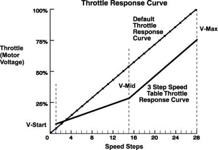
If you want to create a more realistic throttle response curve, you can set up a 28 step loadable speed table. Loadable speed tables define the percentage of motor voltage applied at each of 28 digital speed steps. By programming a value for each of the 28 steps, you can set up a customized throttle response curve for each individual decoder equipped locomotive. The shape of this curve defines the "feel" of the decoder's throttle response.
You can use the 3 step method for some locos and the 28 step method detailed here for other locos on your layout, you do not have to choose only one method or the other.
High Resolution 28 Step Speed Tables CV65-95
If you want more precision in setting up throttle response curves for some or all of your locos most Digitrax decoders have a 28 step speed table option. With this method, you must program values for up to 32 different CVs as detailed below. This can be time consuming but you only have to do it once, since the settings will be remembered by the decoder until you change them.
Most Digitrax decoders use the 28 steps programmed and interpolate them so that in operation, they look like 128 speed steps for even smoother operation!
28 Step Speed Table Programming Example
1. Program CVs 65 through 95 and CV29 with CV values from the table below.
2. After programming the table values, program CV29 to a value that enables the loadable speed table. If you want to disable the loadable speed table later, just program CV29 to a value that disables the speed table and you will return to 14, 28 or 128 speed step operation (the speed table is still remembered and can be re activated by programming CV29 to enable the speed table again later). For example, setting CV29 to the value of 16 will enable the 28/128 step speed table, enable analog mode conversion, set the normal direction of travel of the loco and enable 2 digit addressing. This CV value is just one of many choices to enable the loadable speed table and control the other variables handled by CV29 at the same time.
3. Once the speed table is programmed, you can scale the entire speed curve by using the forward trim value (CV66) and reverse trim value (CV95). These CVs act like a "volume control." When you use these trim values, you don't have to reload the entire 28 step table if you want to change, for example, the maximum forward speed from 45 scale mph to 80 scale mph. Changing the forward or reverse trim values will scale all the values used in the table, in the corresponding direction, by the value programmed into the CV. Using different forward and reverse trim values allows for many different combinations. The trim values can increase the table values from 100% up to 200% or decrease them from 100% down to 2%.
If you are using the PR1 programmer, programming a speed table is as simple as "drawing" the throttle response curve you want on the screen and pressing the "Send" or Program button.
When speed matching locos, get the first loco running the way you like and then match subsequent locos to it. We strongly recommend that you keep a running list of the CVs and CV values you have programmed for each decoder.
When CV29 is set to enable a loadable speed table, any V-max (CV05) or V-mid (CV06) values programmed are not used by the decoder when it determines how much motor voltage to apply. Non FX decoders don't use V-start (CV02) when a loadable speed table is enabled. Non-FX decoders don't run loadable speed tables in 128 speed step mode. To run non-FX decoders with a loadable speed table, you must run them in 14 or 28 speed step mode. Set their CV29 value to x10/016, x11/017, x14/020, x15/021, x30/048, x31/049, x34/052 or x35/053 and status edit these decoders to a value of 10, 20, 12, or 22. FX decoders have start voltage and 128 speed step table operation available. The following table is an example of a loadable speed table. Many Digitrax customers have asked us why we can't formulate tables like this for specific locomotives. The reason is simply that each and every locomotive is different and the same table does not work for all locos.
Table V: Example, Loadable Speed Table
|
Used For |
CV # |
HEX |
DECIMAL |
Register Mode Value |
|
Page 17=PL |
||||
|
Kick Start |
CV65 |
x01 |
001 |
1 |
|
Forward Trim |
CV66 |
x80 |
128 |
2 |
|
Step 4 value |
CV67 |
x0A |
010 |
3 |
|
Step 5 value |
CV68 |
x0E |
014 |
4 |
|
Page 18=PL6 |
||||
|
Step 6 value |
CV69 |
x12 |
018 |
1 |
|
Step 7 value |
CV70 |
x16 |
022 |
2 |
|
Step 8 value |
CV71 |
x18 |
024 |
3 |
|
Step 9 value |
CV72 |
x1c |
028 |
4 |
|
Page 19=PL6 |
||||
|
Step 10 value |
CV73 |
x20 |
032 |
1 |
|
Step 11 value |
CV74 |
x24 |
036 |
2 |
|
Step 12 value |
CV75 |
x28 |
040 |
3 |
|
Step 13 value |
CV76 |
x2c |
044 |
4 |
|
Page 20=PL6 |
||||
|
Step 14 value |
CV77 |
x32 |
050 |
1 |
|
Step 15 value |
CV78 |
x36 |
054 |
2 |
|
Step 16 value, |
CV79 |
x3c |
060 |
3 |
|
Step 17 value |
CV80 |
x40 |
064 |
4 |
|
Page 21=PL6 |
||||
|
Step 18 value |
CV81 |
x46 |
070 |
1 |
|
Step 19 value |
CV82 |
x4c |
076 |
2 |
|
Step 20 value |
CV83 |
x52 |
082 |
3 |
|
Step 21 value |
CV84 |
x5A |
090 |
4 |
|
Page 22=PL6 |
||||
|
Step 22 value |
CV85 |
x60 |
096 |
1 |
|
Step 23 value |
CV86 |
x6A |
106 |
2 |
|
Step 24 value |
CV87 |
x72 |
114 |
3 |
|
Step 25 value |
CV88 |
x7E |
126 |
4 |
|
Page 23=PL6 |
||||
|
Step 26 value |
CV89 |
x88 |
136 |
1 |
|
Step 27 value |
CV90 |
x94 |
148 |
2 |
|
Step 28 value |
CV91 |
xA2 |
162 |
3 |
|
Step 29 value |
CV92 |
xb2 |
178 |
4 |
|
Page 24=PL6 |
||||
|
Step 30 value |
CV93 |
xc6 |
198 |
1 |
|
Step 31 value, |
CV94 |
xdA |
218 |
2 |
|
Reverse Trim |
CV95 |
x80 |
128 |
3 |
|
Configuration Register |
CV29 |
x16 |
022 |
5 |
|
Page Register |
None |
None |
001 |
PL6=Page register |
Notes for Table V
1. The Kick Start CV provides for a short voltage "kick" when you start the locomotive decoder from 0 speed. A value of 00 turns this option OFF.
2. If you program Forward Trim (CV66) & Reverse Trim (CV95) to CV values of 128 (x80 Hex), 000, or 001 you will get no scaling effect. A trim value of 255 (xFF Hex) will give 200% scaling of the table entry value.
3. A final scaled table value of 255 (xFF Hex) represents 100% applied motor voltage or Full speed. A value of 128 (x80 Hex) represents 50% applied motor voltage, i.e., the actual table step entry is multiplied by the appropriate Trim value to yield the final scaled table value that defines the voltage to apply to the motor.
4. The steps defined in the table are for the 28 speed step mode. Step 4 is the first motion step in the 28 speed step system. Step 31 is the "full throttle" speed step. When setting up the decoder to run 14 step mode, only every second entry in the table is used. When 14 speed steps are used by the command station, the decoder will automatically use the correct CVs and their CV values from the speed table.
5. The suggested CV values given in the example speed table will give a throttle response curve that most US users will find useful. Once you have loaded the example table, feel free to modify the CV values to suit your own preferences.
Please use 3 step speed tables for all DZ121 & DN121 Series Decoders, because of size constraints in their processors, they do not support 28 step speed tables.