Product Support for: Detection & Signaling -> Signal Decoder (SE8C)
View the Product Page for the SE8CSE8C Plug 'N Play Signal Decoder make it easy to add prototypical signaling to your layout. The SE8C can drive as many as 32 signal heads with many popular LED signal types. It can also be used to control up to 8 slow motion turnout machines as either turnout control or control for semaphore type signals. Easy modular Plug 'N Play and additional accessories make it simple to add signaling to your layout.
43 Articles Found for SE8C
Q: I would like to know about SE8C and signals on non-DCC layouts. A: The SE8c is a signal driver for your layout. You can operate signals manually with any LocoNet Throttle and Command Station. Or, in your case, the SE8c can drive signals automatically with detection and compatible computer software such as RailRoad & Co. or JMRI.You will need detection devices to identify the presence of trains, a computer interface such as the PR3, a computer program supplying the signaling logic and the SE8c driving the signal heads themselves. Note that in a LocoNet environment, the SE8C supports detection: DS01 ...
What are the power requirements of a SE8C? Any power supply that can provide 12-15 volts either AC or DC with a minimum current rating of 100 ma is all that is necessary to power a single SE8c. Digitrax recommends the PS14 for powering the SE8c. A single PS14 has the ability to power two SE8c’s. When connecting multiple SE8c’s to a single power source the total maximum current requirement of the power source is computed by multiplying the number of SE8c modules by 100 ma (Example: 3 SE8c’s would require a 300 ma power supply - 3x100=300). The edge ...
Security ElementsThe Digitrax Signaling System is organized around the concept of what we call "security elements", which are similar to what U.S. prototype railroads call "plants" or "interlockings". The Digitrax SE8C signal decoder displays aspects for up to 32 heads for 8 individual security elements (plants) using either a LocoNet Throttle or a computer with compatible software. When used with associated occupancy detectors and compatible software, the SE8C can be set up to protect the turnout with signals as shown by the example below. Note that trains can move from A to B, A to C, B to A or ...
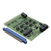
Individual signal heads are driven from connections marked DRV1 - DRV8. Although these are typically connections to individual signals, they can serve more than one signal as necessary. The ID Button is used to set the individual SE8C board ID. If using more than one such circuit board, each must be assigned a unique number so that the system recognizes it. The Option Button is used to customize the SE8C. LocoNet Jacks provide a data channel for the SE8C.
If you want to reset the SE8C to its factory settings, follow this procedure: No track power is required for testing, but you will need a working LocoNet connection and throttle, or a PC running DCC control software that is connected to LocoNet. a. Press and hold the Option Button until the red LED starts to blink. b. Release the button, the red and green LEDs will blink alternately indicating that you are in Option Switch programming mode. c. Go into SWITCH mode on your throttle or PC. d. Select Switch 20. e. Close and then Throw the switch to ...
Q: We will be using your SE8C's for signaling. Should we use the SE8C to control our slow motion switch machines, or should we use your DS64s for that function? A: Both products will do the job. How you plan to use them on your layout will help you decide which is better in your situation. Here are some things to consider in making your decision:The SE8C will drive 8 slow-motion switch machines while the DS64 will drive four. If you have a large number of switch machines in a specific area, the SE8C might be a better choice, since the ...
I would like to use a Tomar Searchlight Signal such as model # 858. It has three color LED for each head. The SE8C manual shows the wiring example for bi-color LED signals. Is the SE8C able to control the three color LED signals as well? The bi-pole LED's can be used to produce a yellow "Approach" indication. The SE8C sends an AC signal to the LED, alternately lighting both the red and green sides to make a yellow (or "amber") Indication. Please see below: "A2" is connected to produce an approach (yellow) indication. You may find that the yellow ...
We recommend testing your new SE8C prior to installation on your layout. The following testing procedures will help familiarize you with the general operation of the SE8C. Track power needs to be ON, a working LocoNet connection and a throttle or PC running DCC control software. Pre-Installation Set-Up 1. Solder one wire from a 12V AC or 15V DC power supply to Pin 3 and the second wire from the power supply to the Pin C on the 44-Pin edge connector; this powers the SE8C. Digitrax manufactures the PS14, which is appropriate for this installation. Multiple SE8Cs can be powered ...
The SE8C uses switch addresses to operate the signals, so you may need to change some factory settings to make it work in conjunction with turnouts that are already installed on your layout. Be sure that when you configure the SE8C that the switch address ranges you select to operate the signals do not conflict with other devices, like DS64s, that are already installed. We strongly recommend that you keep accurate documentation of the address ranges used to control all devices on the layout to avoid conflicts that might cause problems. Without this record it can be very difficult to ...
Connecting BD4 to an SE8C?The BD4 is a block occupancy detection device designed as an add-on device that can take advantage of the LocoNet hosting capability of the SE8c signal decoder. It is connected this way: The installation of a BD4 is relatively simple. Looking at the BD4, you will find a 5-point terminal block on one end and two (LED1 and DS1) 10-pin (5x2) headers on the other. There are three termination areas: a) The 5-point terminal block (left) is for the interconnection between the rail power source and the rails. b) The LED1 10-pin header is ...
The Nemo Junction module has a total of seven color light signals that regulate the flow of train traffic through this interlocking plant. Controlling the Signals with SE8C The SE8C is the signal driver, sending current to the various LED's of the color light signals. Each signal is operated via switch commands from the Zephyr. The SE8C has eight Driver Sockets, identified as DRV1 - DRV8. : A Signal Driver Cable (a 10-conductor ribbon cable) is plugged into a SE8C Driver Socket to control as many as four signal heads per Driver Socket. Each signal head can display 4 lighting ...
BD4 Output Each BD4 is situated between the PM42 Power Manager and the railroad. The DCC signal passes from the DCS50 Zephyr, through the Power Manager, through the BD4 to the track to the locomotive. When a locomotive (or equipped car) is present in a track segment, the BD4 also sends out occupancy information, in two ways. Occupancy Information Output LED1 The LED1 10-pin header is for testing the status of power to the rails and block occupancy with the LED indicator which is included with the BD4. The LED1 can also be used for panel indicator lights using LED's. ...
Q: Can the SE8C slow motion turnout controllers operate multiple turnouts from one output? A: No. The slow motion connection was originally intended to be used with single slow motion drives for semaphores, part of the overall design of the SE8C signal driver. Since only one semaphore is operated, the circuitry was not designed to handle heavier loads than that single drive.
Do you have a recommend wiring procedure for the 44-pin edge connector on the PM42 and SE8C?PM42, PM4, BDL168, BDL16, BDL162 & SE8C use a 44-pin edge connector. Connecting wires securely to this connector requires soldering skills. For connections to the 44 pin connector, Digitrax recommends using 16 gauge stranded wire. For all other soldering connections, Digitrax recommends 14 gauge (AWI) stranded wire for electrical connections on your railroad. 1. Use individual short lengths of 16 gauge wire to connect to the 44 pin connector. 2. Strip and tin both ends of the wire. 3. Bend one end into ...
Q: What is the output voltage to the LED's and the inline resistor value. A: The typical output of the SE8C ranges between 4.5 and 5.0 volts DC; it varies a bit depending on conditions. The signal mast base kit (SMBK) and the terminal strip mounting kit (TSMK), both have 100 ohm resistors built into the base.
44 pin connectors with screw terminals were originally designed by a company called LWH3. Their products allow you to install the PM42, BDL168, and SE8C without having to solder to the 44 pin connector. The product line was sold to Accu-Lites. These products are available online directly from Accu-Lites at www.acculites.com
Detection Section Inputs DS01 to DS08 (see below) are inputs from occupancy detectors that provide at least +5V (max 22V) when occupied, and 0V when unoccupied. The SE8C sends occupancy messages to LocoNet when these inputs change. If these detection section inputs are not disconnected, they will report “unoccupied”. Occupancy reporting can be turned off by changing OpSw 13 to closed.
My signals are supplied with current limiting resistors and require 12v max to operate. What are the voltage outputs from the SE8C and does this differ depending on the supply (15V AC or 12V DC). The output voltage is 5 volts, regardless of the input power. It is powerful enough to drive LED's, but it cannot handle incandescent lamps.
The SE8C can be used in 2 aspect mode. The signal control address range will be in blocks of 32 instead of 64.To use this mode set Option Switch 02 to closed (OpSw02=c).
The individual signal heads are connected to the SE8C with 10 conductor ribbon cables. Depending upon which way you assemble the ribbon cables, Pin 1 can be either the brown colored conductor (called Phase A) or the black colored conductor (called Phase B). To maintain your sanity it seems easiest to be consistent when choosing either conductor, but there is no "wrong" answer. In the example below, the ribbon cable is being set up using the brown cable as Pin 1, thus it is being configured as "Phase A" The table below shows the various connections which result when setting up ...
The SE8C can drive position light type signals such as those used by the Pennsylvania Railroad and the B&O RR and the N&W RR. Leads from the signals can be soldered directly to the pads on the Signal Mast Base (the Terminal Strip Mounting Kit can also be used for interfacing your signals with the system.)You can use either common anode or common cathode signals. We recommend that you use either all common anode or all common cathode signals on your layout for consistency in the set up procedure on your layout. If you are using the terminal strip option ...
SE8C - Semaphore and Broadcast Control Switch Address Ranges Semaphore Control Switch AddressRange 16 Per SE8C Broadcast Control Switch Address Range 2 Per SE8C SW01-Sw16 Sw01-Sw02 Sw17-Sw32 Sw09-Sw10 Sw33-Sw48 Sw17-Sw18 Sw49-Sw64 Sw25-Sw26 Sw65-Sw80 Sw33-Sw34 Sw81-Sw96 Sw41-Sw42 Sw97-Sw112 Sw49-Sw50 Sw113-Sw128 Sw57-Sw58 Sw129-Sw144 Sw65-Sw66 Sw145-Sw160 Sw73-Sw74 Sw161-Sw176 Sw81-Sw82 Sw177-Sw192 Sw89-Sw90 Sw193-Sw208 Sw97-Sw98 Sw209-Sw224 Sw105-Sw106 Sw225-Sw240 Sw113-Sw114 Sw241-Sw256 Sw121-Sw122 Sw257-Sw272 Sw129-Sw130 Sw273-Sw288 Sw137-Sw138 Sw289-Sw304 Sw145-Sw146 Sw305-Sw320 Sw153-Sw154 Sw321-Sw336 Sw161-Sw162 Sw337-Sw352 Sw169-Sw170 Sw353-Sw368 Sw177-Sw178 Sw369-Sw384 Sw185-Sw186 Sw385-Sw400 Sw193-Sw194 Sw401-Sw416 Sw201-Sw202 Sw417-Sw432 Sw209-Sw210 Sw433-Sw448 Sw217-Sw218 Sw449-Sw464 Sw225-Sw226 Sw465-Sw480 Sw233-Sw234 Sw481-Sw496 Sw241-Sw242 Sw497-Sw512 Sw249-Sw250 Sw513-Sw528 Sw257-Sw258 Sw529-Sw544 Sw265-Sw266 Sw545-Sw560 Sw276-Sw274 Sw561-Sw576 Sw281-Sw282 *Addresses above 1000 require ...
How do I set up the SE8C to control semaphores? Installing Semaphore Type Signals with SE8CThe SE8C can be set up to use its 8 turnout motor drive outputs to run 8 three-position semaphore (arm type) signals using slow motion turnout control machines (such as the TortoiseTM machines) as actuators. These 8 semaphore signals are available in addition to the standard 32 LED signal heads on the 8 signal control cables and occupy a separate semaphore address control range.The SE8C automatically sequences the three possible mechanical arm positions to match 3 aspects of red, green and yellow using a position ...
SE8C - Default Switch Address Range Usage For Board IDs 01-36 Board ID(Press ID Button, set Sw# for Board ID number) Slow Motion Turnout Machine Switch Address Range8 Per SE8C Signal ControlSwitch Address Range 4 Aspects Per Head64 Per SE8C Signal ControlSwitch Address Range2 Aspects Per Head 32 Per SE8C 01 (factory setting) Sw01-Sw08 Sw257-Sw320 Sw257-Sw288 02 Sw09-Sw16 Sw321-Sw384 Sw289-Sw320 03 Sw17-Sw24 Sw385-Sw448 Sw321-Sw352 04 Sw25-Sw32 Sw449-Sw512 Sw353-Sw384 05 Sw33-Sw40 Sw513-Sw576 Sw385-Sw416 06 Sw41-Sw48 Sw577-Sw640 Sw417-Sw448 07 Sw49-Sw56 Sw641-Sw704 Sw449-Sw480 08 Sw57-Sw64 Sw705-Sw768 Sw481-Sw512 09 Sw65-Sw72 Sw769-Sw832 Sw513-Sw544 10 Sw73-Sw80 Sw833-Sw896 Sw545-Sw576 11 Sw81-Sw88 Sw897-Sw960 Sw577-Sw608 12 Sw89-Sw96 Sw961-Sw1024* Sw609-Sw640 ...
SW01 to SW08 are inputs that allow a local switch mounted on the layout to operate the slow motion turnout machine. For example, SW01 when connected to the +VE sensor common (Pin 2 in figure) will reverse the voltages on SMTM1A and SMTM1B to change the position of turnout 1. SW02 controls local turnout 2 , etc. For each connection to +VE sensor common the slow motion turnout machine swaps direction and a Switch message is sent to LocoNet to report the new position of the turnout. This local control can be disconnected by setting OpSw 15 to closed, in ...
Connecting BD1 to a DS54, DS64 and SE8c? The BD1, block occupancy detector (replaced in 2004 by the BD4) was designed as an add-on device, which took advantage of the block occupancy message generating (over the LocoNet) capabilities of the DS54. The BD1 is also compatible, for the same purpose, with the DS64 and SE8c. The following diagrams indicated how to connect the BD1 to the rails, rail power source, and the Digitrax DS54, DS64 and SE8c. Note: The wires that connect the BD1 to the rails and rail power source are characterized as two heavy, uninsulated, and polarity neutral wires.
The TSMK, Terminal Strip Mounting Kit, includes 2 terminal strip boards with resistors for easy installation. The Digitrax Terminal Strip Mounting Kit makes it simple to connect any scale or model signal to the Digitrax signaling system without soldering. Simply connect the wires from the signal to the TSMK’s screw terminals and plug it in to the SE8C’s Signal Driver Cable. Using the Terminal Strip circuit boards You can attach any of a variety of types of model signal masts in any scale you choose to the Terminal Strip Mounting Kit. The Terminal Strip Mounting Kit has 10 screw terminals ...
I am putting the finishing touches on my 10 x 20 foot H0 railroad. It is a copy of the Cajon Pass, Salt Lake & Santa Fe RR by John Armstrong (#86 in the 101 Track Plans by Linn Westcott) [Kalmbach Publishing, ISBN 0-89024-512-6; still in print]. I have decided to go with DCC and my local hobby store recommended Digitrax. The layout is in my basement, I will be the only operator, the plan has 54 track switches (34 NJ International twin coils and 20 Tortoise turnout motors). Can you give me an idea as to what equipment I ...
Digital Command Control (DCC) has specific electrical requirements that must be provided for your layout control system to operate properly.Input PowerAll DCC systems require an external power supply. Digitrax manufactures several power supplies for our command stations and boosters: The 3 Amp PS415 (the Zephyr Xtra power supply) The 5 Amp PS515 for all Digitrax 5 amp command stations and boosters The powerful 20 Amp PS2012 can be used for multiple 5 and 8 amp command stations and boosters Additionally, the PS14 is available to power various other devices for your railroad. Digitrax strongly encourages you to use our power supplies to insure satisfactory ...
This document outlines the power requirements for Digitrax LocoNet accessories. To simplify wiring, Digitrax recommends providing individual power supplies for like accessories. For example a power supply or power buss which only powers the PM42s. A power supply or power buss used solely to power multiple DS64s. UR9x and UP5 panels can be daisy chained provided adequate current is provided to properly power all the panels. Through the use of individual power supplies, the chance of Ground Loops or sneak paths back to ground is minimized. Using individual power supplies will also make troubleshooting much easier. Many Digitrax LocoNet ...
The 10-Pin Signal Mast Bases that are part of SMBK and used as test signals with the SE8C have two connections marked Aux Hi and Aux Lo (Pins 2 & 9). These connections are not currently implemented and are reserved for future use.
The subject of railroad signaling is a fascinating one. Signals provide a margin of safety and protect the train crews, freight and passengers on the railroad . Grade crossing signals also protect the general public from collision with moving trains. Signal operation relies upon three basic elements: Detection of trains Operation of the signals Operation Logic Signaling is a complicated topic, far beyond the scope of this knowledge base. But Digitrax offers several items which will help you with creating a realistic signal environment. Detection determines the presence or absence of trains. Both the BDL168 and BD4 will ...
My question is: How do I mount the PM42? Do I need a special housing in order to mount it under table? It appears to me that mounting it flush against a surface would prevent, or make it extremely difficult, to attach the 44-pin connector. Digitrax manufactures three devices which have a 44-pin connector. These are the BDL168 (and its predecessor the BDL16), the SE8C and the PM42 (and its predecessor, the PM4). These best approach to mounting these devices is to screw the connector directly to the wiring panel board. Drill mounting holes in the end of the 44-pin ...
Under what conditions can the PR3 be used as a Stand Alone LocoNet Terminator? The PR3 is so designed so that it can be configured to act as a stand alone LocoNet controller in the event that a Digitrax command station is unavailable for the control of a series of LocoNet compatible devices. There are two major situations that would require the PR3 to act as a stand alone LocoNet controller. The first situation is where one of the many advanced features offered by the LocoNet and the various LocoNet compatible devices is desired to be used on a layout ...
A cascaded route is where the last command of a route triggers the next route; this is also known to some as a nesting route. With the capacity of 8 turnouts per route, it becomes necessary to cascade routes if more than 8 turnouts are involved in a route. To highlight these possibilities, we use a very complex scenario with many turnouts and possible routes. Cascading routes allows the setup of long routes without the need for a computer. Since some routes exceed the capacity of 8 turnouts, the remaining turnouts of the long routes are setup in the second ...
As originally conceived, the Texas & Southwestern was set up with a very simple DCC system. The railroad uses a DCS50 Zephyr as its command station and booster. The Zephyr is connected to a central power bus, and all tracks, stationary turnout decoders and the automated reverse loop unit are connected to it. Likewise, the LocoNet connections are a series of simple cable connections starting at the Zephyr and ending at the last Universal Panel. The T&SW works well with this arrangement, but there are additional devices that will enhance the operation of this railroad. Digitrax PM42 Power Management System ...
Q: I am the only operator. There will be no others. I wish to use block detection for signaling. However, I find that I cannot use the BD4s in the way I thought they could be used. My question, must I divide my simple layout into blocks (which DCC says you don't really need) in order to use the BD4's and SE8C together? A small basic layout can be operated in the DCC environment without dividing the railroad up into power districts. In this scenario, you will use one command station/booster to power the entire layout. As your power consumption ...
Train detection and the related signaling can be a complicated affair. However, it becomes easier if you analyze things and break them down into their component blocks. The whole idea is to protect trains from each other, regulating their movements by the use of signals which tell train crews what to do or what to expect. Train detection identifies which segments of track are occupied by a train. For the real railroads, track detection sections can be very short (such as at track junctions) or very long (such as in rural environments). Train speed and frequency of trains are also ...
I am now constructing an N-Scale layout with Digitrax DCC system. I know SE8C and two-heads signal mast supplied by your company are applicable for a entry signal mast for the both of main and siding (branch) lines. However, I don't know how the signal mast is used in the case of "more than two" siding lines. For example, the next picture was taken in Powder River Basin (Converse Jct.) in Wyoming State. TS, Japan In this picture, some two-heads signal (mast) can be seen. In every signal mast, the top signal head will be for a main line. But, ...
The DB200+ is the 8 amp booster. It has NO command station capability. This booster was designed for adding power to layouts that run lots of locos and for large-scale layouts where power requirements are heavy.DB200+ Control PanelNOTE: DB200+ front panel graphics may vary from those shown here. Internally the booster is the same. These instructions are written for both versions of graphics as well as the DB200+ OPTO optoisolated version of the booster. About the Green Jumper WireEvery DB200+ is shipped with a green jumper wire on the front panel Booster Terminal Plug connecting Synch & Ground or ‘Config ...
This article stops in a strange place?? We need to find the rest of it and split it up into meaningful chunks. Also needs meta stuff Troubleshooting in General:Regardless of the guides, manuals, tips, suggestions, experts or whatever, troubleshooting can occasionally degenerate into a vast chasm of darkness and confusion. It would be impossible to cover all the areas that have, can or may cause problems. This is a general guide to identifying and resolving problems with Digitrax Complete Train Control. Keep Good Records:Although it may seem to be a pain while setting up your Digitrax system, keeping layout records ...
Digitrax Complete Train Control By Zana & A.J. Ireland Digitrax Complete Train Control makes reliable, realistic train operation and simplified layout wiring a reality. Digital Command Control is incorporated within the Digitrax system to let you control multiple trains independently on the same section of track without blocking. In the real world, engineers control the speed and direction of real trains. Engines operate under their own power independent of the track. Each engine has its own motion characteristics like how fast it speeds up (acceleration) and how long it takes to slow down (deceleration). A locomotive's performance is influenced by ...