Nemo Junction
Case Study: Nemo Junction
Background
The world is filled with places like Nemo Junction, a crossing between two railroads which is protected by a signal interlocking plant that also serves as an interchange point between these railroads. Cars destined for places to and from another railroad are exchanged at places like these. The interchange has been described as being the ideal model railroad industry because any type of car can be found there, heading toward places that are not on the model railroad itself.
Nemo Junction is based upon a real place, a location in Illinois identified on the timetable of the Santa Fe Railroad as "Nemo", Latin for nothing. At one time, the other railroad that met the Santa Fe was the Chicago & Northwestern, and before that it was the Minneapolis and St. Louis, and before that it was the Iowa Central. Now, Nemo is just a point on the Santa Fe, with the C&NW tracks lifted in the 1980's.
Even when these two railroads were active, there were few structures present at this junction, and we have taken a few liberties with the track layout, making the two railroads cross at grade instead of the overpass that is still present there today. Likewise, the locale has been improved, adding an oil dealer and railroad structures, where, in reality, Nemo was simply a meeting point in the middle of flat farm land. Nemo Junction is an Everyman kind of place, like countless crossings throughout the world.
The Concept
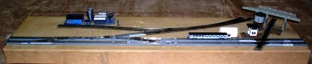
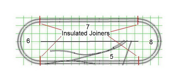
The core element of Nemo Junction is the junction itself. Our model of Nemo is an opportunity to illustrate a variety of Digitrax components used to produce a realistic railroad scene. With this segment, we will show power management, turnout control, train detection and signal operation. The model is a 48 inch by 12 inch N-Scale module which uses Kato Unitrack for a double track mainline with a branching track that leads to an imaginary interchange point with another railroad. The railroad which crosses the double track main is a dummy, simply there for displaying the effect of a second railroad.
The junction module is part of a larger N-Scale modular model railroad:
The various modules of the railroad have individual scenes, but the real action will take place at the junction. It is here that trains can change tracks and conduct switching operations.
Initially, the railroad will simply be a "runner", but as we add features, it will become an "operator".
Nemo Junction - The Basic Wiring
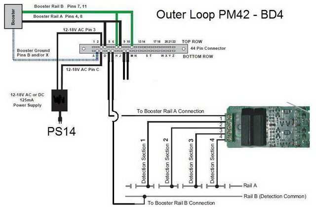
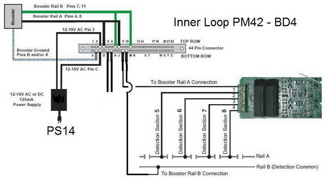
Although this is a simple railroad, it will have some advanced features. When the railroad's sectional modules are first assembled, the electrical connections are simple. The railroad will be controlled with a DCS50 Zephyr, using a PM42 Power Manager for short circuit protection. One section of the PM42 will control the inner oval of track, a second section of the PM42 will control the outer segment. This is done so that if a train derails on one loop, the train operation on the other loop will not be affected. Because the DCS50 is rated at 2.5 amps, the PM42 must be adjusted to work with the Zephyr (please see related article, below).
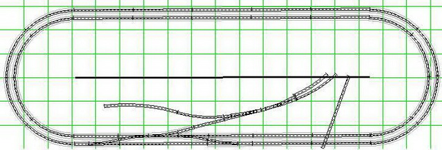
Initially, the Nemo Junction modular railroad will simply be two ovals of operational track plus the junction. However, it is anticipated that the railroad will have signals, so the modules are divided up into 8 sections with insulated rail joiners, four pair on the inside oval and four pair on the outside.
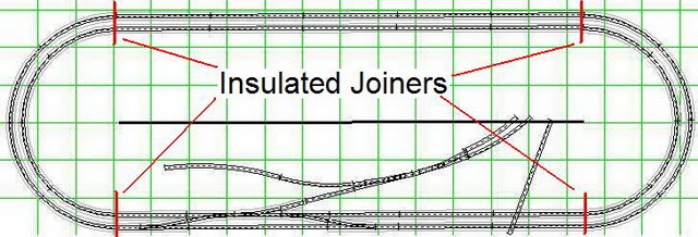
Feeder wires are then routed back to the Nemo Junction module. These feeder wires will be ganged together initially, and then later individually connected to two BD4's, which are used for train detection. To insure accurate connections, each segment of track is given an identification number; this is used only to identify the wires which connect to the Digitrax components.
The outer loop is divided up into four sections, numbered 1 - 4.
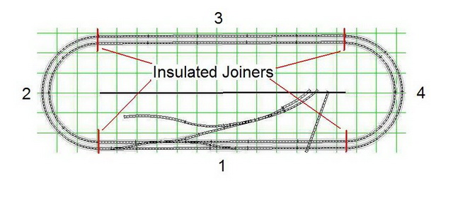
The inner loop is also divided up into four sections, numbered 5 - 8.
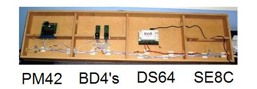
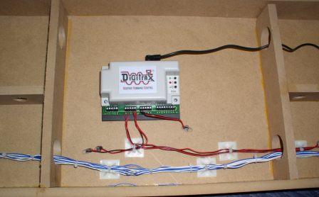
Here is the bottom layout of the various components:
With the DCS50 Zephyr now connected to the PM42 Power Manager, Nemo Junction can begin operating as a model railroad. We are going to continue further, establishing the groundwork for color light signals which protect the junction. The Digitrax device used for this feature is the BD4. Nemo Junction will be equipped with two BD4's, one for the outer loop of track and the second for the inner loop of track, detecting all 8 sections of the railroad mainline.
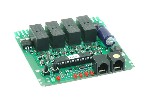
The BD4
The BD4 is a Quad Occupancy Detector for 4 detection sections. It will detect the presence of any powered locomotive, unpowered freight rolling stock equipped with resistor wheel sets or passenger rolling stock equipped with internal lighting. The BD4 has outputs for panel mounted LEDs to display occupancy. It also transmits occupancy information to your LocoNet System; in the Nemo Junction example, two BD4's will be connected to an SE8C. This will later be incorporated into a signal system for the Junction.
How It Works
The BD4 can detect the presence of a locomotive or lighted car on four segments of track. The railroad has been divided up into eight sections of track; each of these is a "Detection Section". So, the Nemo Junction module uses two BD4's (alternately, you could use a BDL168).
The Outer Loop
The outer loop uses one BD4 for detection and is assigned to sections 1 - 4:
The first BD4 is connected to the PM42 in this way:
The Inner Loop
The inner loop uses the second BD4, which is assigned to sections 5 - 8.
The second BD4 is connected to the PM42 in this way:
Note: In the interest of consistency, the Nemo Junction modules consider "Rail A", which is the detection rail, to be the rail closest to the front of the module, which is the protocol recommended by N-Trak. If you are building a stand-alone railroad, you need only make sure that you are consistent with the location of Rail A and Rail B. If you plan to interface your railroad with other railroads, such as at train shows, you need to make sure that your railroad is built to the same connection standard.
Here, the final connections:
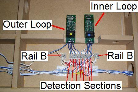
The individual detection section wires are connected from each BD4 through a barrier strip to the detection rails of the railroad. The Rail B wires for the common rail of each loop are joined at a terminal strip, one for the inner loop and a second for the outer loop. The Rail A and Rail B wire pair for each BD4 is then connected back to the PM42:
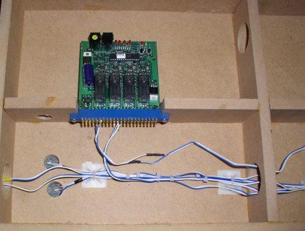
Additional connections to PM42 from the Zephyr (Rail A, Rail B, Ground), LocoNet and connections to the PS14 power supply are not in place in this photograph.
Although the Nemo Junction modules are simple loops of track and the DCS50 Zephyr has an internal circuit breaker, the railroad is equipped with a PM42 Power Manager:
Adding the PM42 allows the two loops of the railroad to operate independently. If there is an electrical problem on one loop, such as when a train derails, operations can continue on the other loop.
Powering PM42
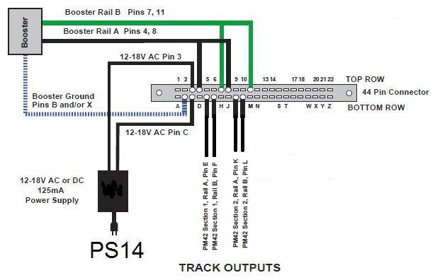
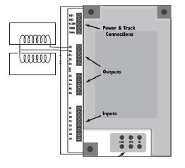
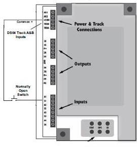
The PM42 is powered with a PS14; because of electrical timing issues, it is important that the PM42 has its own dedicated power supply. This power supply is connected to Pin 3 on the top row and Pin C on the bottom row.
Connecting PM42 to the DCS50 Zephyr
A ground wire is connected from Pin B to the Ground connection on the DCS50 Zephyr command station. The Rail A and Rail B output connections for the Zephyr are connected to the "Top Row" of the PM42's 44-Pin Connector; this is also referred to as the "Component Side". The Rail A output is connected to both Pin 4 and Pin 8. The Rail B output is connected to both Pin 7 and Pin 11.
Track Connections From PM42
The track power output connections for the PM42 are located on the "Bottom Row" of the PM42's 44-Pin Connector; this is also referred to as the "Non-Component Side". The Outer Loop electrical connections are from Pins E & F. The Inner Loop electrical connections are from Pins K & L.
To insure reliability, it is important to make sure that the connections to the rails from E & K and F & L are properly oriented with each other. That is, E & K are made to the left rails of each track and F & L are made to the right rails of the track. If the connections are made incorrectly, a short circuit will occur when a train passes from one loop to the other. It doesn't matter which is which as long as you are consistent with your connections.
(It should be noted that this is not an insurmountable problem; the short circuit issue can be corrected by making the PM42 sections "Autoreversing". It is easier however, to get the orientation correct in the first place.)
After initial testing to insure reliable train operation, these connections will be moved from a direct connection to the track to two BD4 Occupancy Detectors:
Additional connections to PM42 from the Zephyr (Rail A, Rail B, Ground), LocoNet and connections to the PS14 power supply are not in place in this photograph.
Configuring PM42
Once the PM42 is in place, you will need to configure it to operate with Zephyr. While a trip current of 3 amps will work with most boosters, the Zephyr is only a 2.5 amp unit, so the PM42 must be reconfigured to trip at 1.5 amps. Otherwise, the Zephyr's booster will trip before the PM42, shutting down all the sections of track controlled by it, not just the one section controlled by the PM42 that has been affected.
It is recommended to set the trip speed for the PM42 sections to “faster" for short circuit management and "fastest" for auto-reverse. Since we are only using two sections of the PM42, only four OpSw's need to be changed. To change the trip current and sensitivity (trip speed) you must change Option Switch settings on the PM42. The factory setting for all Option Switches is t (thrown). You should change OpSw03, OpSw5, OpSw11 and OpSw 13 all to c (closed).
The related article "PM42 - Programming Op Switches with a Zephyr (DCS50)" is in the Related Articles section, below. We found it helpful to print out this article and have it near at hand when we programmed the PM42 on the workbench.
The purpose of a signal interlocking is to provide safe operation, protecting trains from the movements of other trains.
Interlocking Signals
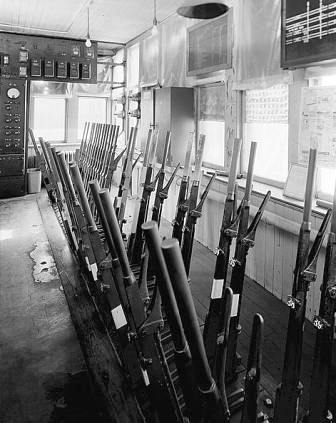
In the case of Nemo Junction, there are trains which simply pass though, trains which change tracks, trains which cross other tracks and other trains that enter and exit. The signal interlocking, or plant, protects the movements of these trains with a series of colored light signals. In an earlier time, these signals could have been semaphores.
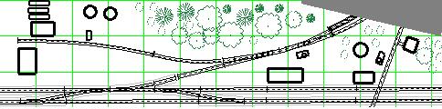
Depending upon the era, these train movements could have been controlled by a signal tower operator in the tower building which is adjacent to the crossing. In a later era, the Nemo interlocking plant could be operated from a central location, many miles away. That central location would control many trains over large portions of the railroad. In either case, there is some sort of track diagram that is used for control purposes. Here is the track diagram for Nemo Junction:
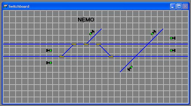
This operator's diagram uses small icons which represent the tracks and turnouts which are controlled by the system, along with icons which are used to show signal locations and indications. The real signals are more complicated. Here, the signal locations for the Nemo interlocking.
The signals at this interlocking are Absolute, which is to say, that a red signal means Stop & Stay. Typically, two lights in a vertical arrangement indicate an Absolute signal. These signals regulate train movement through the Nemo plant.
Signal Operation The SE8C is used to manage the operation of these signals, but a computer program will supply the signaling logic. Before the computer logic is established, the signals must be connected to the SE8C. |
Nemo Junction - Connecting BD4 to the SE8C
BD4 Output
Each BD4 is situated between the PM42 Power Manager and the railroad. The DCC signal passes from the DCS50 Zephyr, through the Power Manager, through the BD4 to the track to the locomotive. When a locomotive (or equipped car) is present in a track segment, the BD4 also sends out occupancy information, in two ways.
Occupancy Information Output
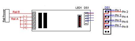
LED1
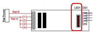
The LED1 10-pin header is for testing the status of power to the rails and block occupancy with the LED indicator which is included with the BD4. The LED1 can also be used for panel indicator lights using LED's.
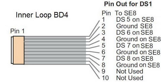
DS1
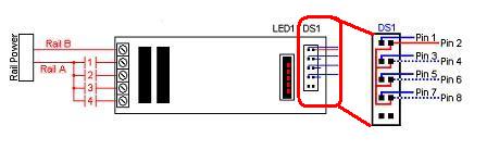
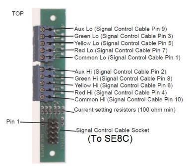
The DS1 10-pin header of each BD4 is connected to the SE8C.
Outer Loop Connections
Pins 1, 3, 5 and 7 of the DS1 are the respective outputs for detection blocks 1, 2, 3, and 4 of the Outer Loop.
Using a section of ribbon cable and a socket from the SDCK - Signal Driver Cable Kit, the BD4 is connected to the SE8C. A segment of ribbon cable is cut to the distance from the BD4 to the 44-pin edge connector of the SE8C. One end of this cable is fitted with a 10-pin socket from the SDCK.
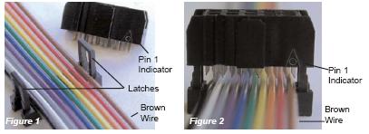
The SDCK socket is then connected to the BD4 so that Pin1 corresponds to the brown wire, making it easy to identify the different DS1 connections of the BD4 at the 44-pin connector of the SE8C.
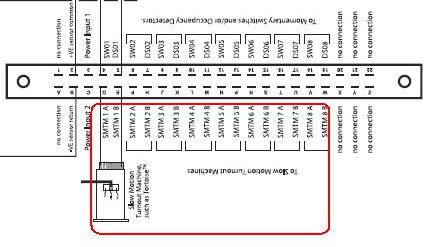
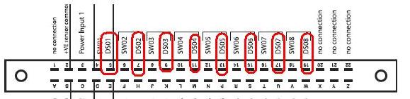
The Nemo Junction Outer Loop's BD4 is connected to pins 5, 7, 9 and 11 of the SE8C's 44-pin edge connector; on the SE8C pin-out diagram, these are identified as "DS01", "DS02", "DS03" and "DS04". The ground connection of the Outer Loop's BD4 (Pin 2, or 4, or 6, or 8, or 10) is the common wire of the BD4 and is connected to pin B (-VE sensor return) of the SE8C's 44-pin edge connector.
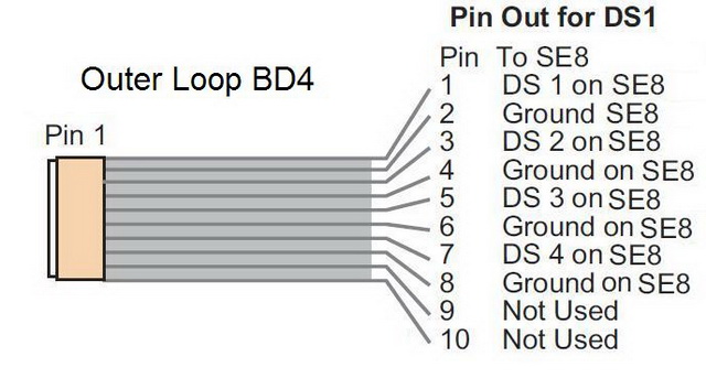
The corresponding wire colors, if Pin1 is connected to the brown wire:
- Pin 1 - Brown
- Pin 3 - Orange
- Pin 5 - Green
- Pin 7 - Purple
The -VE sensor return connection can be made with Pin 2 - Red.
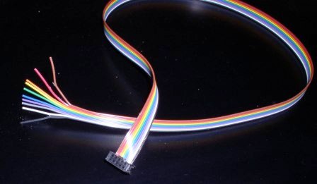
Here, a completed cable:
Inner Loop Connections
The same process is repeated for the Inner Loop BD4, which is connected to pins 13 ("DS05"), 15 ("DS06"), 17 ("DS07") and 19 ("DS08") of the SE8C 44-pin connector.
In this way, the Detection Sections for both the outer and inner loops of the railroad now feed track occupancy information to the railroad's LocoNet via the SE8C. A computer program will take that information and apply signaling operation logic. This is how a railroad signal interlocking operates.
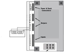
Nemo Junction - Turnout Control
Nemo Junction has several track turnouts. The turnouts which are related to the operation of the signal interlocking plant will be controlled by a single DS64. Most of these turnouts are Kato and could be controlled with DS51K1's, but a DS64 was chosen so that direct connection can be made to the railroad's LocoNet
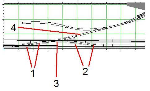
The DS64 can control up to four turnouts. In the case of Nemo Junction, there are two pair of turnouts that allow trains to change from one mainline to the other, numbered 1 and 2.
Each pair will be connected to the DS64, so that when one turnout is operated, the corresponding turnout of the crossover will also operate in tandem.
Turnout pair 1 are connected to DS64 points 1R & 1G.
Turnout pair 2 are connected to DS64 points 2R & 2G
Turnout 3 allows trains to leave the mainline and enter the interchange tracks; this also gives access to the industry siding. It is connected to 3R & 3G.
Connection 4 of the DS64 will be made to a split-rail; this is a device that is frequently used in interlockings to protect trains from accidental train movements. The idea is that it is better for a car or locomotive to derail in a controlled fashion rather than have it roll onto a busy mainline where it would cause much greater damage. It is connected to position 4. Because the split rail uses a two-solenoid machine rather than the Kato-type machine to operate, it is connected to 4R, 4G and P+, in this fashion:
There are two more turnouts on the Nemo Junction module. These will remain manually controlled, which would be typical for the situation. In fact, only the turnout leading to the industrial siding will operate, since the other turnout leads to imaginary tracks of the interchange.
Here, the final assembly:
Turnout 4 has yet to be connected, and the LocoNet has not yet been established on the modules. If the turnouts throw in the wrong direction, the red and black wires are swapped for each of the Kato turnouts.
Programming DS64
Since the turnouts being controlled are solenoid turnouts, the DS64 does not need to be programmed for different turnout motors. However, the Nemo Junction module includes an SE8C, which is used for signal control, so it will be necessary to set the DS64’s board ID so that the computer program used to operate the junction's signals will get the necessary turnout information used with the signal's logic. In this example, the DS64 Board ID was set to an arbitrary value of "10".
Keep track of the Board IDs you have programmed and make sure each one has a unique ID. The larger the model railroad, the more devices which are used, so good record keeping helps prevent problems down the road.
Likewise, the turnouts controlled by the DS64 need to be numbered. You can set the DS64's Switch Address of each of these turnouts four to any value from 01 - 2048, taking care to avoid duplication. We chose to use "1", "2", "3" and "4" for the turnouts. When the SE8C is added later, it will have Switch Addresses which are different.
Powering the DS64
The DS64 is connected to a PS14 power supply and also connected to the railroad's LocoNet.
Push Button Control
At a later date, a push button panel may be installed to give local control for the turnouts. The connections are made with a "normally open" button switch that is connected between the "S1", "S2", "S3" or "S4" terminals and the "Common +" terminal. This is how an individual button would be connected:
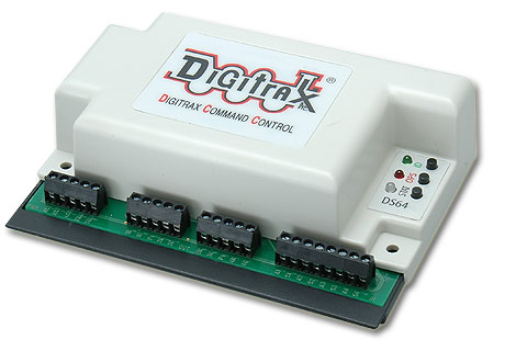
The Nemo Junction module uses an SE8C Plug 'N Play Signal Decoder.
The SE8C can be a complicated device, but if you individually consider the different features of this stationary decoder, you can set it up to make your railroad operate in a very realistic manner. The SE8C stationary decoder incorporates several useful features:
- Controls signal indications
- Controls 8 slow-motion switch machines (for either semaphores or turnouts)
- Has 8 inputs for train detection
- Has 8 inputs for local control of the slow-motion switch machines
In the Nemo Junction application, we will use the signal indication output and train detection input features of the SE8C. At this stage of the project, two BD4's have been connected to the 44-pin edge connector of the SE8C; this is how train location information is introduced onto LocoNet. Later, we will connect the signals to the SE8C.
Addresses Used by the SE8C
The SE8C uses three sets of addresses:
- The signal outputs
- The slow-motion switch machine outputs
- The sensor inputs.
Board ID
To coordinate these different addresses, it is important that the SE8C have a unique Board ID. The SE8C uses switch addresses to operate the signals and slow motion turnout motors, so when you configure the SE8C, the switch address ranges you select to operate the signals must not conflict with other devices. Each Board ID represents a combination of addresses for the signal outputs, slow motion outputs and the train detection inputs.
For a railroad as basic as Nemo Junction, this is a relatively simple matter and we will stay with the Factory default setting of 01.
For Board ID number of 1:
- The signal addresses are Sw257 - Sw320.
- The slow-motion switch machine outputs Sw01 thru Sw08
- The sensor input addresses are 1 thru 8.
When you change the SE8C's Board ID number, these address ranges will change.
In the case of more complicated railroads, each additional SE8C, BDL168 and DS64 must have a unique Board ID to avoid conflicting operations. If two devices share the same Board ID, the operation of one device will also result in the operation of another device that has the same ID.
We recommend that you keep accurate documentation of the address ranges used to control all devices on the layout to avoid conflicts that might cause problems. Without this record it can be very difficult to debug problems. Please see the related articles below.
Signal Outputs
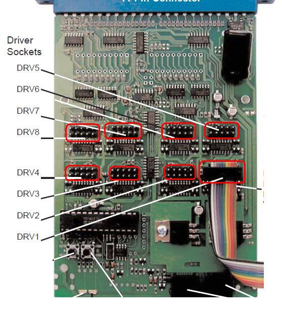
The computer program which controls the signal indications must know which signal to operate and what indication that signal is to display. Each SE8C uses a number of switch addresses to operate the different signals it drives. The signals are connected to the SE8C via 8 Driver Sockets on the circuit board itself, identified as DRV1 - DRV8.
Slow-motion Switch Machine Outputs
The original intent for these outputs was to drive slow-motion semaphores, but others have used these same outputs to drive slow-motion switch machines such as the Tortoise brand. Again, there are a number of output connections, from edge pins on the SE8C's 44-pin Connector, identified as SMTM 1A & SMTM 1B through SMTM 8A & SMTM 8B.
Sensor Inputs
The SE8C receives sensor inputs from detection devices; we are using two BD4's for our example, but the BDL168 could also be used. There are a number of input connections to edge pins on the SE8C's 44-pin Connector, identified as DS01 - DS08. (Note that if you were to use the BDL168 instead of the two BD4's, you would have used only 1/2 of the train detection outputs from the BDL168.)
Momentary Push Button Inputs
Not used in this example, but available with the SE8C are 8 momentary inputs, identified as SW01 - SW08. These could be used for local control of signals by using push buttons, or they could be used for momentary inputs from magnetic reed switches. Again, information coming from these inputs would be put onto LocoNet as a Sensor message.
Signal Control
Initially, you will test the operation of the SE8C with a DT400 throttle. A test signal and completed cable is included with the SE8C for this purpose. Although you can control the signals with a throttle such as the DT400, computer control is a more common approach. To make the signals work properly, the computer program needs to know where the trains are located, so the BD4's used in the Nemo Junction example are a partial source of that information. The computer program also needs to know the position of the turnouts; since the DS64 does not offer turnout position reporting, there are several approaches to this issue.
Later in this series, we will briefly discuss two of the available computer programs, Railroad & Co. and Java-based JMRI.
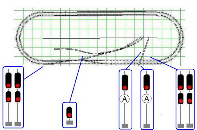
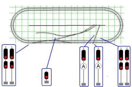
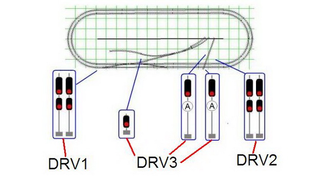
The Nemo Junction module has a total of seven color light signals that regulate the flow of train traffic through this interlocking plant.
Controlling the Signals with SE8C
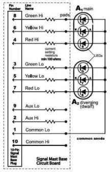
The SE8C is the signal driver, sending current to the various LED's of the color light signals. Each signal is operated via switch commands from the Zephyr. The SE8C has eight Driver Sockets, identified as DRV1 - DRV8. :
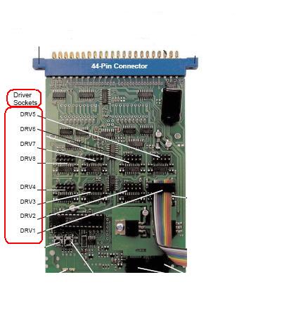
A Signal Driver Cable (a 10-conductor ribbon cable) is plugged into a SE8C Driver Socket to control as many as four signal heads per Driver Socket. Each signal head can display 4 lighting aspects, red (stop), green (clear), yellow (approach) and flashing yellow (advance approach). The signal is operated by sending a switch command from Zephyr to the individual signal head address.
Using the default settings of the SE8C, Driver Socket DRV1 controls signal head A1 with SW257 and 258. That is, you put the Zephyr into Switch Mode, select switch address 257 and send a "Closed" command; the signal turns green. Sending a "Thrown" command to address 257 turns the signal to the red indication. In the same manner, sending a "Thrown" command to switch address 258 turns this signal to yellow. A "Closed" command makes the signal show a flashing yellow indication.
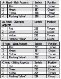
Using the default settings of the SE8C, the entire SE8C is controlled by addresses 257 - 320. Driver Socket DRV1 controls a total of four signal heads, using switch addresses 257 - 264. The SE8C documentation includes this illustration:
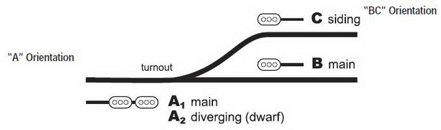
Note that the signal heads are identified as A1, A2, B and C. Although this illustration shows the four signal heads in one specific area, the SE8C could control four signal heads in different areas as long as they are connected to the same 10-conductor ribbon cable. Also, note the terms "A Orientation" and "BC Orientation"; how the individual signal is connected to the 10-conductor ribbon cable determines which switch addresses are used for an individual signal. For DRV1, here are the available switch addresses:
Once the installation is completed, a computer program will be used to coordinate the train occupation information with the signal indications and all that we are looking at here will be handled behind the scenes. The SE8C comes with a test signal which you can use to experiment with the different actions of the SE8C:
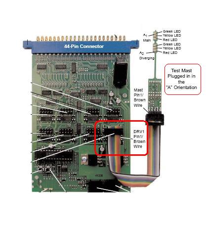
Here, a close-up of the test signal:
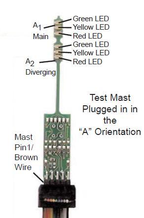
In this illustration, the signal heads are A1 and A2; if the signal were plugged into the cable in the opposite orientation, the signal heads would be B and C.
The Signal Head Schematic
The electrical schematic for each of the two head signals looks like this:
Although this may look intimidating, note the small comment at the bottom of the schematic:
Because the SE8C and the TSMK use 10-pin cable connections, wiring these signals is quite easy.
TSMK
The Terminal Strip Mounting Kit includes 2 terminal strip boards with resistors for easy installation. Each terminal strip board can handle from 1 to 4 signal heads.
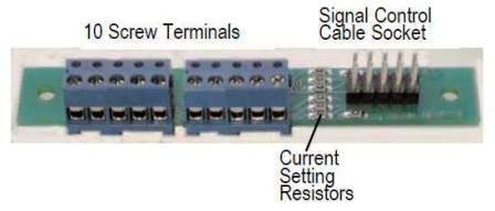
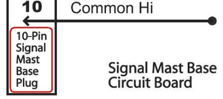
The 10-pin cable from a Driver Socket of the SE8C is connected at Signal Control Cable Socket of the TSMK. The individual signal heads are connected to the screw terminals at the other end of the TSMK.
Note that the terminals of the TSMK correspond to the descriptions of the signal head schematic.
Connecting the Signals
Once the identification of the various signal heads has been completed, each is connected by way of a 10-conductor ribbon cable. Using the Signal Driver Cable Kit (SDCK), the ribbon cable is fitted at each end with a 10-pin plug; one end is plugged into the SE8C and the other is plugged into a Terminal Strip Mounting Kit (TSMK). The TSMK has screw terminals into which the individual wires for each signal are connected.
The Color Light Signals
- There are two sets of paired signals for the two track main line, one set for eastbound trains and the other set for westbound trains.
- Two signals govern approaching trains on the imaginary railroad that crosses the double track main line.
- A dwarf signal which regulates trains approaching from the interchange and entering the two track main line railroad.
Of the seven color light signals used at Nemo Junction, only five will actually change indications; four on the double track mainline and the siding dwarf signal.
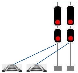
The four active mainline signals have two heads:
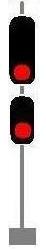
The westbound pair of signals will be connected to DRV1. The eastbound pair of signals will be connected to DRV2.
The Dwarf Signal regulates train movements from the interchange track onto the main line:

The dwarf signal will be connected to the SE8C with Driver Socket DRV3.
Since the North / South single track railroad is a dummy railroad, the two single-head signals will not change their indications.
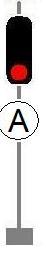
However, the LED's of these signals still need to be illuminated, and we will use two of the remaining connections of DRV3 for that purpose.
Layout at a glance
- Submitted By:
- Riley O'Connor
- Scale:
- N
- Era Modeled:
- 1960's-1980's
- 1 x ZEPX (Zephyr Xtra)
- 1 x PM42 (Quad Power Manager)
- Used for Power Management
- 1 x DS64 (Quad Stationary Decoder)
- 1 x SE8C (Signal Decoder)
- 2 x BD4 (Occupancy Detector for 4 detection sections)
- If supersonic decoders are used, you may wish to substitute BDL168 for detection.