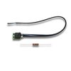
Product Support for: Accessories -> Tester for Decoders & LocoNet Cables (LT1)
View the Product Page for the LT1It consists of a harness with 6 conductor Telco type wire with a male plug, a tester with a female 6 conductor jack, and a 100 Ohm 2 watt protection resistor.
14 Articles Found for LT1
To Test LocoNet Cables With an LT11. Unplug the wire harness from the LT1.2. Plug one end of the LocoNet cable you want to test into the LT1.Note: When making your own LocoNet Cables, it is important to make them in a consistent manner. At Digitrax, the white wire is always on the right side of the plug when the plug is viewed with the clip at the top.3. Connect the other end of the LocoNet Cable being tested to any powered Digitrax Booster’s LocoNet Port A or B. Be sure you have at least one Digitrax throttle plugged in ...
1. Disconnect the wire harness from the LT1.2. Plug one end of the LocoNet cable being tested into the LT1.3. Connect the other end to the cable into on of the LocoNet ports on your DCS50. Make sure the Track Status Indicator Dot is lit.4. All four LEDs on the LT1 will light if the cable is good. LEDs may not all be the same brightness, this is normal. NOTE: Only three LEDs will light if the Track Status Indicator Dot is not lit.5. If any of the LEDs fail to light, recrimp the plugs on the LocoNet cable and ...
The LT1 is a simple decoder tester. Decoder Testing Instructions1. Prepare the cable for use in the testing procedure, by stripping the insulation from the Red, Green, Black, and Yellow wires. The Blue and White wires are not used and can be cut off the harness.2. Twist the RED and YELLOW wires together. Twist the BLACK and GREEN wires together. 3. Hook up decoder as shown in Diagram 2.4. Use your throttle to select the decoder and run it in the forward direction.5. One of the two center LEDs will light as the motor voltage from the decoder increases. Use ...
Follow these simple instructions to determine the best location/s on your layout for installing your UR panels for the best possible infrared or radio reception. With LocoNet, you can use Infrared, Duplex Radio and Simplex radio individually or in any combination on your layout.You'll need to be able to observe whether your command station is receiving commands from the UR panels when you are installing infrared or radio receivers and transceivers. Your Digitrax command station makes it easy to determine when the system is receiving a signal and when it is not. You can observe the NET LED and the Track Status Indicator or your ...
This article stops in a strange place?? We need to find the rest of it and split it up into meaningful chunks. Also needs meta stuff Troubleshooting in General:Regardless of the guides, manuals, tips, suggestions, experts or whatever, troubleshooting can occasionally degenerate into a vast chasm of darkness and confusion. It would be impossible to cover all the areas that have, can or may cause problems. This is a general guide to identifying and resolving problems with Digitrax Complete Train Control. Keep Good Records:Although it may seem to be a pain while setting up your Digitrax system, keeping layout records ...
Before sending your Digitrax Command Station or Booster in for repair try these simple steps to see if you can “bring it back from the dead” and save a possible trip to the repair shop.1. Nothing is respondingIf there are NO LEDs lit on the front panel of the Command Station or Booster: Check the power supply to the unit to make sure that it has not been knocked loose in the power socket and that the socket is powered. Check the connections from the power supply to Track A and Track B connections on the front of the unit ...
Q: I connect my DT400 to my DCS100 and it works fine, but when I add a DB150 working as a booster the DT400 stops working. What is wrong? A: A number of things may cause this, so you can use the diagnostic features of the DT400 to solve this problem. Experience has proven that the most common LocoNet problem is related to pins 3 and 4. By following this diagnostic procedure, you can narrow down to the source of the problem. Starting with DT400 without a battery [The throttle has no battery for this test to assure it executes ...
The DCS50 Zephyr displays three types of error messages: Short circuit shutdown occurs when the DCS50 detects a short circuit in the power district where it is connected to the layout. This can be a loco that has derailed or picked a switch or some other conductive material lying across the tracks. In this case you will see “o”s walking across the display from left to right. Once the short is cleared, the DCS50 will resume normal operations. Current overload occurs when the DCS50 has reached its 2.5 Amp current limit. In this case you should run fewer locomotives or ...
LocoNet typically supports a total cable length of up to 2,000 feet with no two devices connected by more than 600 feet of cable. LocoNet wiring is totally free-form. We do not recommend looping LocoNet back on itself.Making your own LocoNet Cables is simple and cost effective. LocoNet wiring consists of readily available wire and connectors. LocoNet uses flat 6 conductor wire and 6-pin RJ12 connectors. This kind of wiring is typically used for telephone wiring. Most Digitrax dealers can make up LocoNet cables for you. If you plan on wiring a large layout, you may want to invest in ...
LocoNet is Digitrax's method of communication between LocoNet compatible devices on a model railroad layout. LocoNet compatible devices are designed to work together on the network, and in some cases can also accept DCC commands from the track, but often go beyond the scope of simple DCC train control. LocoNet is a peer-to-peer Ethernet type multiple access network. Because of its design architecture, it is very robust and powerful. Layout implementation is simple and wiring is free form with minimal limits. LocoNet is designed to run an unshielded 6 conductor ribbon cable. Digitrax recommends using flat, six-conductor telephone wire ...
Your Super Empire Builder Starter Set contains: The DB150, which is the system’s DCC command station. It generates the DCC signals that control decoders and other devices on your layout. The DB150 is also a DCC booster. Boosters receive DCC signals from the command station, amplify them and put them on the track along with the power from the transformer to run the locomotives. You can have several boosters on your layout to provide additional power to run more locos. Depending upon the set, there is either a DT402 or DT402D (duplex radio throttle), which is the DCC throttle that ...
Q: I recently split my layout in half, with a DB150 acting as a booster powering one side and a DCS100 powering the other. I'm trying to reconnect the bus feeders to the rails, which all worked properly before the split. Now when I reconnect the feeders there is no short indication, BUT when a loco goes over the insulated gap between the two sections, a short occurs. A: This is a common issue when the first booster is added to a DCS100/DCS200 command station. MOST DCS100/DCS200 command stations come from the factory set with Rail A & Rail B connections that are the opposite ...
Here are several things to check if you are having trouble with the BDL168: Proper Wiring Be sure that you have NOT connected pin 11 to pin M, as this can prevent proper LocoNet communication. Check to make sure not wires are touching adjacent pins. Follow the wiring diagram closely. Packet Reception Be sure the green ID LED is ON & is “winking” off about every 2 seconds. This means that correctly formatted DCC packets are being decoded from the left most (Railsync) pin of the RJ12 LocoNet socket. For DCC detection, the same DCC packet signal that drives the ...
Digitrax Complete Train Control By Zana & A.J. Ireland Digitrax Complete Train Control makes reliable, realistic train operation and simplified layout wiring a reality. Digital Command Control is incorporated within the Digitrax system to let you control multiple trains independently on the same section of track without blocking. In the real world, engineers control the speed and direction of real trains. Engines operate under their own power independent of the track. Each engine has its own motion characteristics like how fast it speeds up (acceleration) and how long it takes to slow down (deceleration). A locomotive's performance is influenced by ...