Here are several things to check if you are having trouble with the BDL168:
- Proper Wiring
Be sure that you have NOT connected pin 11 to pin M, as this can prevent proper LocoNet communication.
Check to make sure not wires are touching adjacent pins. Follow the wiring diagram closely.
- Packet Reception
Be sure the green ID LED is ON & is “winking” off about every 2 seconds. This means that correctly formatted DCC packets are being decoded from the left most (Railsync) pin of the RJ12 LocoNet socket. For DCC detection, the same DCC packet signal that drives the booster must be connected to the RJ12 socket's left most pin.
If you are using LocoNet and you do not see the green LED blinking pattern described, check to be sure that the system is powered up and your LocoNet cable connections are good. You can use an LT1 to test the LocoNet cables if you suspect there is a problem with them.
If the green LED on the BDL168 is not lit, check the external power connections.
- Mode Indication
The winking on the green ID LED indicates the primary BDL168 mode.
A single wink indicates standard Digitrax compatible Direct Home track wiring and detection logic will be used.
A double wink indicates Common Rail wiring and detection logic is to be used. For Common Rail, all 4 BDL168 zone connections must be made to the System Common ground point.
Be sure the BDL168 configuration is appropriate for your usage.
- Occupancy Debug
Use the LT5 Tester provided with your BDL168. 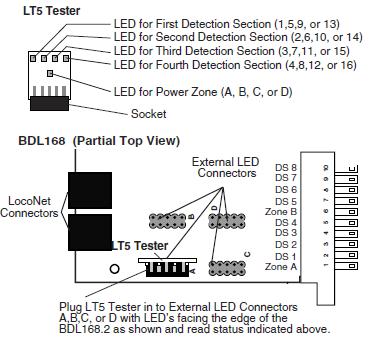
By plugging the LT5 into one of the 4 occupancy LED headers (marked A,B,C & D in the figure above), you can see the state of the zone and occupancies for that header. This allows you to easily check the zone sensitivity (typically 22 Kohms to give detection). This also aids in the determination of detection number and activity for a track detection section.
Many detection problems are related to wiring problems or poor connections to the detection section rather than to the actual BDL168. By using the LT5, you can eliminate the wiring issues from the equation and be sure that the BDL168 is set up correctly. Remember, if the zone power is OFF, the occupancy LEDs should be set up so that they will be on to be sure that signaling systems or a CTC/dispatcher will see the detection section in its most restricted aspect.
- LocoNet Debug
If you are using LocoNet for reporting, be sure that the configuration is correct for your usage. In normal operations the red “option” LED will blink ON briefly when valid LocoNet messages are seen confirming a good LocoNet network connection.
- Analog Locomotives
The motor inductance of analog locomotives may in some installations cause cross talk among the BDL168 detection sections. The addition of a 220ohm, 3 watt, wire wound resistor between the booster track terminals (Rail A and Rail B on Digitrax boosters) will typically reduce the effect of this cross talk. Simply use a leaded resistor as a jumper between the booster's Track A & Track B terminals.