Direct Home Layout Wiring
Digitrax strongly recommends direct home wiring where each power district and its booster are electrically isolated.
This method of wiring has safety advantages and makes troubleshooting problems easier.
In addition, direct home wiring makes detection work more prototypically.
With direct home wiring, the BDL168 can determine and indicate whether any of its 4 zones is powered or not (possibly short-circuited) even when there is nothing on the rails in the detection sections.
The BDL168 factory-set logic causes the detection sections to show "occupied" if the associated zone's power is off (because in this case, detection is not possible).
This factory setup matches typical prototype detection safety practices.
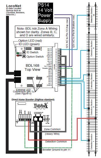
The Figure below shows an example of a direct home wiring layout with a single power district with multiple detection sections. Zone A with 4 detection sections (1-4) and zone D with one detection section (16) has been wired in this example.
Wiring the BDL168 for a Digitrax Direct Home Wiring Layout
1. After mounting the 44-pin connector to the board, label the top of the 44-pin connector for easy identification of the wires, using zone letters (A,B,C,D) and detection section numbers (1-16). Note, these are not the same as the pin identification numbers that are already molded on the connector. Make sure to double check the connector orientation before plugging in the BDL168 board to avoid possible damage that can result if it is plugged in using the incorrect orientation. (Please see related article below).
Hint: Some users assign each BDL168 board a letter designation to use with the detection section number for tracking outputs. For example the first BDL168 board would be labeled “A1”, “A2”...“A16” on the wiring panel terminal strip, on the rough layout and on the layout diagram for easier troubleshooting.
-
Solder one wire (AC1) from a 12-16V AC or DC power supply to the pin 12 and the second wire (AC2) from the power supply to the pin N on the BDL168's 44-pin connector. This powers the BDL168. Multiple BDL168 units can be supplied by a single shared supply as long as you provide at least 100mA for each BDL168. This power supply should not power any devices other than BDL168s.
-
Solder the ground wire from the Digitrax booster ground or common (case) to pin 11 of the 44-pin connector. Nothing is connected to pin M.
-
The end of the wire from each zone common and detection section should be stripped approximately 1/4” and inserted through the holes in each pin pair on the connector as indicated in Table 1 and Figure 4. Solder the wire to each pin. The zone common connections to the booster should be as short as possible and relatively heavy gauge, since they are common to all four detectors in the zone. For example, a 12AWG zone connection to the boost- er should be less than 10 feet for best performance.
-
Plug the BDL168 board firmly into the 44-pin connector.
-
Connect a LocoNet cable into one of the BDL168's LocoNet jacks.
-
Apply power to the unit. The red and green LEDs will light up as power is applied to the unit. The red LED will go out and the green LED will stay on and “wink” off once, approximately every 2 seconds, indicating that it is connected to LocoNet and seeing DCC packets.
The BDL168's option switches are factory set at the values that will work for most direct home wired layouts. You can fine-tune the BDL168's characteris- tics using its option switches which can be set using a Digitrax compatible throttle or a PC with LocoNet compatible software that can control turnouts.