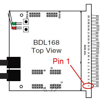
BDL168 Pin Out Configuration:
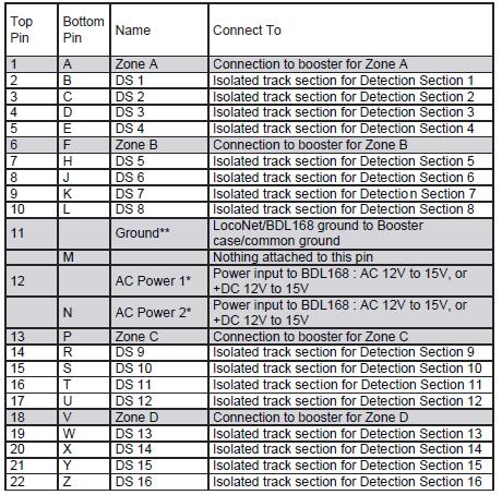
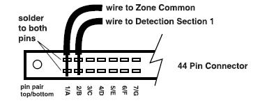
Notes: 1) All connector pins are paired top (component side of the BDL168) and bottom (solder side of the BDL168) except 11/M and 12/N. For 6 Amp current rating with 3 Amp connector pins, track/zone wires must be connected to both pin pairs: e.g. Zone A = pins 1 & A (See Figure below):
2) Letters G, I, O & Q are not used as pin designations on the connector.
3) Power connections should be made to a power supply dedicated to BDL168 use only. Multiple BDL168 units can be supplied by a single shared supply as long as you provide at least 100mA for each BDL168.
4) The Ground connection, pin 11, must be made to the booster for correct BDL168 operation.
Confirm that the 44-pin connector is plugged in to the BDL168 in the correct orientation to avoid damage to the BDL168 when power is applied.