DN163K1C 1 Amp N Scale Mobile Decoder for Kato N scale SD40-2 locos made from year 2006 onward
This product has been replaced by the Mobile Decoder (DN147K1C) and is no longer available. Click here to view the DN147K1C.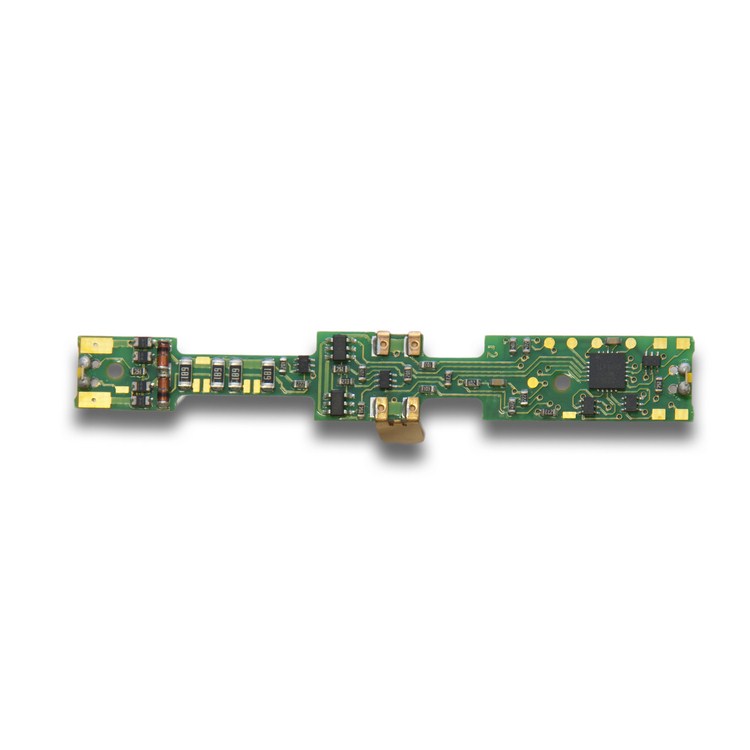
Features:
-
Designed to fit the Kato N scale SD40-2
locos made from year 2006 onward
Specifications
- Current Rating-Motor
- 1 Amp Continuous/1.25 Amp Peak Rating
- Size
- 0.426” x 3.11” w/LEDs x 0.195” (10.8204mm x 78.994mm w/LEDs x 4.953mm)
- Installation
- Board Replacement (read more)
These decoders are made to fit specific locomtoive chassis. Locomotives that have circuit boards that can have decoders installed in place of the original circuit board are made by many manufacturers.
In some cases, locomotive modifications, motor isolation and additional soldering may be required during installation of this type of decoder. Function leads can be added to these decoders using solder pads available on the decoder.
See the instruction sheet for the particular decoder you are using for specific instructions.
Sometimes these are called plug n' play or drop in decoders.
- Function Outputs
- 6-500mA
- Function Type
- FX3 (read more)
Digitrax Real FX3
- Turn functions on and off.
- Head lights and tail lights are automatically reversing unless you make them independent.
- All function outputs have FX generators for prototypical lighting effects and have qualifiers for FX effects and qualifiers for standard on/off functions.
- All Digitrax Series 3 decoders have FX3 type functions.
- FX3 decoders offer full function mapping so you can choose which function (F0-F12) controls each function lead.
- FX3 decoders offer master light switch capability.
- FX3 decoders offer qualifiers for FX function operation qualified by one of the following: the loco's direction of travel, whether F0 is on or off, loco direction and F0, or whether the loco is moving or not. These qualifiers are also available on function outputs that are used as standard on/off functions.
Motor Isolation Note: FX3 decoders have motor isolation protection. If the decoder senses that the motor is not isolated, it will not run the motor. In this case, you will be able to control the loco’s functions but the motor will not work.
Here is an explantion of how the CVs that control FX3 effects work. Most modern Digitrax systems do not use hexadecimal format but it is provided here in case you need it for older systems.
CV 49-52, CV113-116, CV62 & 63: Digitrax Real FX3 Special Light Effects
Decoders with FX3 features have 8 user configurable, independent special effects generators. These are set up by programming CV values as described below. If your decoder is not a “series 3” decoder, please check the spec sheet to determine which type of functions it supports.
FX3 functions incorporate FX generators with additional dynamic and static qualifiers. FX3 functions are fully remappable so they can be controlled by any function key on your system. A master light switch can be set up to turn off all lights on a locomotive. Functions associated with advanced consists can be controlled, too.
Setting Up FX3 Effects On Function Outputs
1. Each function output has an FX3 control CV associated with it. Using TABLE IVa below, determine which CV you need to program to set up an FX3 feature for the function output you are working with. For example, if you want to set up an FX feature on your forward headlight, you will use CV49 to control the FX3 feature for the lamp attached to F0F. Some decoders do not have function output wires attached. See the specific decoder instructions to determine which "pad" on the decoder controls each function. Use thin wire or wire saved during previous decoder installations to solder function output wires to the pads associated with the function you want to use.
TABLE IVa: FX3 Generator CVs
FX3
CV#
Function #
Output Color
CV49
F0/Light Forward (F0F)
White
CV50
F0/Light Reverse (F0R)
Yellow
CV51
F1 Function 1
Green
CV52
F2 Function 2
Violet
CV113
F3 Function 3
Brown
CV114
F4 Function 4
White/Yellow
CV115
F5 Function 5
White/Green
CV116
F6 Function 6
White/Blue
2. Each FX3 effect has a CV value that generates the effect you want and controls how the effect works with respect to locomotive direction and the head light (F0) function.
The FX3 CV value is made up of 2 digits. The second digit determines which FX3 effect will be generated. The first digit determines how the effect will work with respect to the locomotive direction, the head light and other functions. Use TABLE IVb to determine the second digit and Table IVc to determine the first digit of the FX3 CV value to program into the CV selected in step 1.
TABLE IVb: The Second digit of the FX/FX3 CV value determines which FX3 effect will be generated.
FX3 CV value second digit (hex)
FX3 effect generated
x0
No effect, normal function control of lead
x1
Random flicker
x2
Mars light
x3
Flashing head light
x4
Single pulse strobe
x5
Double pulse strobe
x6
Rotary beacon simulation
x7
Gyralite
x8
Rule 17 dimmable headlight, dim when F4 is active or locomotive direction is opposite normal direction of travel (NDOT)
x9
FRED or "end of train" light
xA
Right ditch light on when loco is running forward and F0 is on. When F2 is on, the right ditch light flashes alternately with the left ditch light to simulate ditch light operation at a grade crossing.
xB
Left ditch light. on when loco is running forward and F0 is on. When F2 is on, the left ditch light flashes alternately with the right ditch light to simulate ditch light operation at a grade crossing.
xC-xF
Digitrax reserved for effects expansion.
TABLE IVc The first hex digit of the FX3 CV value determines how the effect generated will behave. For example, two strobe lights can be set up to flash alternately by setting one to phase A and the other to phase B. The strobes can also be set up to be on when the loco is moving forward and off when moving backward.
TABLE IVc: How FX3 effects generated will work
FX3 CV value first digit (hex)
How the FX3 effect generated will work
0x
Forward direction, ON with function ON, effect phase A
1x
Reverse direction, ON with function ON, effect phase B
2x*
Non directional effect, ON with function ON, effect phase A
3x*
Non directional effect , ON with function ON, effect phase B
4x* Master Light Switch F0
Forward direction, ON with F0 ON & function ON, effect phase A
5x* Master Light Switch F0
Reverse direction, ON with F0 ON & function ON, effect phase B
6x Master Light Switch F0
Special Logic for Fwd Ditch Light or Rule 17 dimming Standard Ditch Light Operation
7x Master Light Switch F0
Special Logic for Rev Ditch Light or Rule 17 dimming Standard Ditch Light Operation
FX3 CV value first digit (hex)
How the FX3 effect generated will work
Ax
Speed=0, non directional effect, phase A and function qualifier
Bx
Speed>0, non directional effect, phase B and function qualifier
Ex Master Light Switch F0
Ditch off phase A Alternate Ditch Operation-Off when running flash on with F2
Fx Master Light Switch F0
Ditch off phase B Alternate Ditch Operation-Off when running flash on with F2
3. Program the FX3 CV value from step 2 to the FX3 CV identified in step 1. If you are using the PR1, an FX set up section is available where you can just "point and click" to set up the effects you want to use. The software lets you select which function output and which FX feature you want from a menu so you don' have to use the tables above to determine which CV or CV value to use.
4. For FX3 decoders, you can set up as many as 8 function outputs. All FX3 outputs can be set up with FX3 effects.
5. If you want any function output to remain a simple on/off output, leave it programmed to the factory default of CV value 00.
Customizing FX3 Effects-Rate and Keep Alive: CV62
CV62 lets you control the rate and keep-alive brightness for each FX3 effect you set up. The CV value for CV62 is made up of 2 digits, the first digit and the second digit.
The first digit controls the keep alive/baseline off voltage for incandescent lamps. This value should be between 0 and F. A value of 0 gives no keep alive and a value of F gives maximum keep alive. Values between the high and low allow you to vary whether the lamp actually goes off between light pulses or whether it stays on very dimly or more brightly. (If you are using LEDs, the first digit for CV62 should be 0.)
The second digit controls the rate of the FX3 effects programmed. This value should be between 0 and F. A value of 0 gives a fast rate and a value of F gives a slow rate of operation. We recommend you start with a 4 and adjust it up or down until you get the effect you are looking for.
Ditch Light Hold Over Time CV63
If you are using the ditch light effect in conjunction with F2, CV63 lets you set up a hold over time to control how long the ditch lights continue to blink after F2 turned off by releasing the key on the throttle. Remember that F2 is a momentary key on most Digitrax throttles that will keep function 2 on as long as you hold the key down and then turn function 2 off when you release the key. This allows the ditch lights to be on steady during regular operation and to begin alternate flashing when F2 (usually the horn) is activated and to continue flashing alternately for a predetermined length of time after F2 is released; just like the prototype. A value of 00 yields no hold over time, a value of 40 yields a realistic time of about 5 seconds. A value of 255/xFF yields about 20 seconds hold over time.
FX3 Examples
Any function output on the decoder can be set up for any FX3 effect by programming its associated FX3 CV to the appropriate FX3 CV value. For example, if CV52, the FX3 CV for F2, is programmed with an FX3 CV value of 002/x02, the violet F2 function output will be a Mars light when F2 is turned on for this decoder address and the decoder's direction is forward.
TABLE IVd: FX3 CV EXAMPLES
CVs that affect all FX3 function outputs
Meaning
Recommended
CV# & CV Value
dec/hex
Effect on Decoder
Analog Functions Enable/Disable
(Not applicable for FX3)
13: 207/xcF
All functions F0 though F4 are ON in analog (DC) mode
Configuration Register
29:006/x06
Advanced 28/128 speed step mode, analog mode conversion enabled
Keep Alive/Rate
62:196/xc4
High keep-alive for lamps, Rate 4 for approx. 1 sec FX effect rate
Ditch Light Hold Over Time
63:064/x40
5 Sec Ditch light holdover after F2 is turned OFF
CVs that affect specific FX3 outputs:
Function/
Color
CV# &CV Value
dec/hex
FX3 Effect Generated
F0 Fwd White
49:104/x68
Rule 17 dimmable headlight, directional
F0 Rev Yellow
50:000/x00
Normal directional reverse headlight, NO effect used
F1 Green
51:106/x6A
Right Ditch light, directional. F0 & F2 must be ON for this to operate.
F2 Violet
52:107/x6b
Left Ditch Light, directional. F0 & F1 must be ON for this to operate.
F3 Brown
113:034/x22
MARS light, ON when F3 is ON (If we used {113:050/x32} we would get opposite phase MARS light)
To set up two alternating double pulse strobes on the green and violet function outputs controlled by turning on both F1and F2, program CV51 to a CV value of 037/x25 and program CV52 to a CV value of 053/x35. This is an example of using the alternate effects phases A & B.
For FX3 decoders you have 8 FX3 generators available to use with your function outputs.
Setting Up Static (Non-FX3) Functions with FX3
When an FX3 decoder output is set up for static on/off operation (no FX3 effect), you can use static qualifiers to customize the operation of the on/off function of that output.
In this case, the second digit of the FX3 control CV will always be 0 to set the decoder for static (no FX3)function operation. The first digit is determined by the following table according to how you want it to work.
Static CV value
How The Static Function Output Will Work
000/x00
On/Off Output controlled by function map
016/x10
On/Off Output controlled by function map
032/x20
Forward qualified On/Off Output
048/x30
Reverse qualified On/Off Output
064/x40
F0 qualified On/Off Output (Master Light Switch F0)
060/x50
F0 qualified On/Off Output (Master Light Switch F0)
096/x60
F0 On in Forward Direction qualified On/Off Output (Master Light Switch F0)
112/x70
F0 On in Reverse Direction qualified On/Off Output (Master Light Switch F0)
160/xA0
Speed=0, non directional qualified On/Off Output
176/xB0
Speed>0, non directional qualified On/Off Output
Troubleshooting FX3 effects
Common problems with FX3 set up are:
Trying to program a decoder for FX3 when the decoder does not support FX3. Be sure the decoder you are programming has FX3 features. Digitrax introduced FX3 in 2002 in the “series 3” decoders. Digitrax introduced FX in the summer of 1995 in all of its premium decoders so if your decoder was made before then it does not have FX capability. FX & FX3 decoders use different CVs for controlling the function outputs of the decoder.
FX3 effects don't work as expected. Review the qualifiers you set up for the effect. For example, if the effect is set up to come on only when F1 and F0 are active and the loco is headed in the forward direction, be sure you have met those conditions.
Setting Up A Master Light Switch with FX3 Decoders
For FX3 decoders F0 can be used as a master light switch to turn off all lights in the locomotive when F0 if OFF. To do this set up all functions qualified to be on when F0 is on and off when F0 is off. See Table IVc above and use 4, 5 ,6, 7 ,E, or F as the first digit of the FX/FX3 control CV to enable the master light switch on F0.
- Features
- Series 3 (read more)
Digitrax Decoder Series Numbers
Over the years as technology advanced, Digitrax has added more and more features to our mobile decoders. Also, over time, the industry standards and uses of come CVs have changed. Each of our decoder web pages includes a link to a specification sheet for that particular decoder so that you will know which CVs are used for which features in that particular model.
Digitrax uses series numbers to let customers know which feature set is part of a particular decoder.
The fifth character of each mobile + function decoder part number is the Digitrax series designator. For sound + motor + function decoders we typically use the sixth character as the series designator. There are variations in a few part numbers.
Series 6
Compatible with Digitrax PX series Power Xtenders to keep locos and sound running in the presence of dirty/poor track work.
FX3 outputs optimized for both LED and bulb applications.
FX3 outputs have configurable pulse available on all outputs.
Improved Scaleable Speed Stabilization (BEMF).SoundFX Series 6 Features
Sound decoders available with either 8 bit standard or 16 bit premium sound.
Sound decoders configured for 8 Ohm speakers.
Allows for longer sound fragments.
Available in either standard 3 or premium 4 voice versions.
Auto CV configuration by sound projects
Scaleable Speed Stabilization (BEMF) optimized for sound operation.
Series 5
Sound Bug Compatible: Series 5 Digitrax Decoders add the ability to add sound to regular mobile decoders with Sound Bug. Some Series 5 decoders have sockets for simply plugging in the Sound Bug while others require soldering to wire the Sound Bug to the decoder.
Series 4
First generation SoundFX decoders
Most are mobile, sound and function decoders, some are sound and function only decoders.
Series 3
Series 3 decoders with 6 functions have FX3 function outputs
Torque compensation
SuperSonic motor drive for quiet operation (silent operation)
Support for all DCC programming methods as of the time of release
Operations mode read back capability for CV read back on the main line
Scaleable Speed Stabilization (Adjustable Back EMF)
One Step decoder Factory CV reset (CV08=8 or CV8=9 to preserve loadable speed tables)
Motor Isolation Protection
Transponding
White or Golden Yellow LEDs on decoders that come equipped with LEDs
Series 3 decoders with less than 6 functions have a modified set of features
Series 3 Economy
Digitrax Decoders have all Series 3 features EXCEPT Scaleable Speed Stabilization (BEMF)
Series 2
FX function outputs
Scaleable Speed Stabilization (Back EMF)
Transponding
Series 1
Digitrax decoders have standard or configurable strobe function outputs.
- Warranty
- No Worries Warranty (read more)

Digitrax gives a one year "No Worries" Warranty against manufacturing defects and accidental customer damage
on all Digitrax command stations, boosters, throttles, decoders, power supplies and layout control devices.
That's it! A simple, straightforward warranty with no tricky language!
Repairs are simple, too! Just fill out the form and return your items directly to Digitrax for repair. We'll get them fixed up and return them to you as quickly as possible. Please DO NOT return items for repair to the place of purchase.
Make Sure Your Item Needs To Be Repaired Before Sending It To Us! Many of the units we receive for repair do not need any repairs at all. Before you send any units for repair, please take a few minutes to review our Support Options.
1. Check the Tech Support Depot for help. Search for troubleshooting guides.
2. Click here to send Digitrax Tech Support a message.
Please give your name, e-mail address, phone number and when is the best time to contact you. Please give a complete description of the issue you are having.
Many problems are easily resolved by contacting Digitrax Tech Support without having to send in your unit.
Note: Some Digitrax products are no longer repairable due to unavailability of repair parts. Un-repairable items will be returned to you at no charge with no repairs made.
Please Note: Most of our products are not user serviceable. If a defect or accidental damage occurs, return the unit directly to Digitrax for service. Please do not open the Command Station/Boosters (except for making voltage adjustments or changing batteries per the manuals). Please do not remove the shrink wrap protective sleeves from the Digitrax decoders. Shrink may be peeled back to expose pads for adding function wires.
Accessory items that are not covered under the No Worries Warranty carry a 90 day warranty against defects in materials and workmanship. This includes speakers, wire, cables, battery covers, etc.
Intentional damage and customer modifications outside the scope of instructions provided with the product are not covered by this warranty.
Do NOT send a locomotive with your decoder. If a locomotive is sent to Digitrax, Digitrax will ship the entire package back, unrepaired.