Santa Fe & Western
The Santa Fe & Western is a small simple “out and back” track plan with a small yard. It has a continuous run mainline with two passing sidings allowing you to simulate a great deal of prototype operation. This Case Study concentrates on how to convert this layout from traditional DC to DCC operations. Please note, this case study was originally presented as part of the “Digitrax Big Book of DCC” and it has been reproduced here from that text. This study was originally presented as part of three chapters about DCC Installation based on different layouts. The other layouts discussed were the Norcross Southern and the Brandywine & Benedictine. It is recommended that you read these studies as well as some of the topics overlap.
Santa Fe & Western
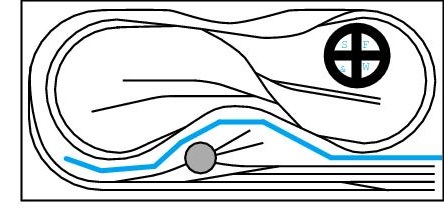
Figure 2-1: Santa Fe & Western track plan
The Santa Fe & Western, shown in Figure 2-1, is similar to layouts described in Atlas Custom-Line Layouts for HO Scale Railroads and Nine N Scale Railroads, both published by Atlas Model Railroad Co. The “out and back” track plan with a small yard and a continuous run mainline with two passing sidings allows you to simulate a great deal of prototype operation. In HO scale the layout would be about 5 by 12 feet. The N scale version would be 38 by 82 inches. Figure 2-2 shows the control panel schematic and the controls and block switches recommended by Atlas for this railroad. These consist of two conventional power packs wired for twin cab control, two Atlas controllers containing a double pole double throw switch (DPDT), one each for the turntable and for the reversing loop section, four Atlas selectors with switches for the fourteen electrical blocks and fourteen Atlas switch control boxes for the eighteen turnouts. This is an example of an existing conventionally controlled layout that can be easily converted to DCC operation.
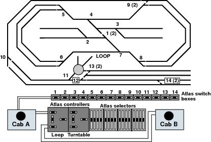
Figure 2-2: Santa Fe & Western control panel and schematic
DCC Components Needed
To convert the Santa Fe & Western to DCC will require several basic DCC components. Most of these components are included in a DCC starter set. All DCC system manufacturers offer starter sets to help make your move to DCC as painless as possible; they have already worked out which components you need to get started and packaged them as starter sets. For this particular conversion, an Empire Builder starter set with a few extra components will be used.
The DCC starter set contains the brain and heart of the system. The DB150 is a combined command station and booster in one enclosure. This particular command station/booster was selected for this installation because it can control more than five trains at once, the maximum number we plan to run on the layout. Since the DB150 can actually control up to 22 addresses simultaneously there is even room for later expansion. The unit’s built-in booster will supply up to 5 amps to the track, plenty for running the trains planned. The DB150 also includes all the configuration, programming and control functions needed for a layout of this size and complexity.
Because this layout is designed for more than one operator, at least two throttles will be needed, one throttle to use when running trains alone and another for visitors. The throttle that comes with the starter set has two separate control knobs so you can control two trains at once on the same throttle. It is a full function throttle that can control all aspects of the layout and its locos and can be used to configure the DCC system itself. The will also be used to program decoders.
For visitors, many DCC users choose a more traditional style throttle like the Digitrax utility throttle. This type of throttle has a single knob potentiometer type throttle with simplified capabilities. It is much easier to teach a visitor who is unfamiliar with DCC to use this type of throttle. Of course if friends bring over their own Digitrax throttles, then they can be used on the layout, too.
Each of these throttles comes with a seven foot long cord. The seven foot cords would make it possible to follow the train around with the two throttles plugged into the command station in the N scale case but, because of the backdrop, it will be hard to see and reach across the layout. If the layout were built in HO scale, the throttle cords just wouldn’t be long enough. So, to make operation easier, provide places where the walk-around throttles can be plugged in on both sides of the layout. Digitrax universal panels, one on each side of the layout, will be used to provide a place to plug in throttles. Each universal panel allows two throttles to be plugged in at once. Six conductor phone sockets can also be used in place of universal panels for additional throttle sockets. This requires more work but could save a little money.
Connect the universal panels to the command station/booster using two six conductor flat telephone cables with RJ12 male connectors on each end. For the Santa Fe & Western, these cables should be about six feet long. You can make these cables yourself, but for a layout of this size, it may be easier buy them ready-made from Radio Shack, Digikey, Home Depot, the local telephone equipment supplier or home improvement store. Often these cables can be purchased from your DCC dealer, too. Either way, make sure that you get six conductor cables with all six pins wired straight through with male connectors on each end. If you aren’t specific, the supplier will probably give you a four pin plug and/or four conductor cable which is commonly used for US telephone connections.
In any case, whatever the source of the cables, they should be tested before use to ensure that they are wired correctly. Every Digitrax starter set comes with an LT1 tester unit for testing both decoders and LocoNet cables.
To test a LocoNet cable:
1. Plug a throttle directly into one of the sockets on the command station.
2. Plug one end of the cable to be tested into the other socket on the command station.
3. Plug the other end of the cable into the LT1 tester socket.
4. Make sure the track power is ON and the speed on the throttle for Address 00, the special address for conventional locos, is set to zero.
5. Look at the tester LEDs.
6. If all four are on, the cable is good.
7. While all the LEDs are on, wiggle the cable at each plug to make sure that there are no intermittent connections and that all the LEDs remain on.
8. If all the LEDs are not on, there is a problem with the cable that must be corrected before continuing the installation. Most often, the problem is with the plug crimped onto the end of the cable. The easiest solution is to remove the old plug and crimp on a new one.
Using the universal panel and plug-in walk-around throttles is the least expensive throttle configuration for the Santa Fe & Western. Radio and/or infrared (IR) equipped throttles could be used instead for wireless operation. For a layout of this size and shape this is probably not really necessary. Radio and infrared capabilities can be added later, they do not have to be installed immediately when the layout is converted to DCC.
The next step in converting the Santa Fe & Western is to provide one or more decoder equipped locomotives to run on the layout. Most DCC systems can run one train with conventional locomotives without decoders. To get the layout running, one or more decoder equipped locos for each additional train will be needed to run on the layout. There are many DCC mobile decoder choices available. Some locomotives come with factory installed decoders. Others are built for simple to install plug-and-play decoders. Still other locomotives must have wired decoders installed.
Finally, to complete the conversion to DCC, you’ll need power to run the trains and the DCC system. Only a few DCC systems include a power supply built into the booster or command station. To provide for maximum flexibility in foreign markets where 110V 60 cycle AC is not standard, most DCC manufacturers do not include an integral power supply for their DCC systems.
The Santa Fe & Western is designed to run two trains on the mainline, a switcher in the yard and a locomotive at the engine terminal all at the same time; say a maximum of five units. Assuming that modern HO or N scale locomotives with modern high performance motors are used, these five units running at the same time will draw 2 to 3 amps all together. Since the existing layout already has two conventional power packs, the accessory AC output from one of them can be used to power the DCC system. The accessory AC output from the other power pack can be used to power the turnouts. If the drain on either power pack is too great, another transformer which can produce 12 to 20 volts AC can be used instead. Transformer kits or ready-made power supplies that output 5 to 10 amps are available from many sources. If the locomotives begin to slow down when more locomotives are added to the layout or if the boosters shut down, this may be a sign that the existing power supplies used are not up to the task.
To sum up, one of the existing power packs will be used as a power supply for the DCC system, a DB150 Command Station/Booster, a Digitrax Advance throttle throttle for general purpose use, a utility throttle for visitors, two Universal Panels to plug in the throttles and a decoder for each DCC locomotive.
Connecting Components
Before actually connecting anything to the Santa Fe & Western, it will be useful to build a shelf below the existing control panel big enough to hold the DB150 command station/booster and with some extra room for two additional DB150 sized components for future expansion of the system.
In order to locate any problems as the DCC components are connected, proceed in a step-wise fashion, testing each piece as it is added to the system. First, disconnect the DC power feed from Cab A to the control panel. Do not disconnect the AC accessory power to the Atlas switch control boxes since it will still be used to provide power for the turnouts. Because of the power draw that occurs each time a turnout is activated, the same power pack is not used for turnout control and to power the DCC system. Next, test to be sure that the switch control boxes still operate the turnouts and that all the blocks are dead for Cab A.
Set all the block or cab switches to Cab B. The DCC system will be wired in place of Cab B. Next, following the instructions which came with the DCC system, connect the AC accessory output of the Cab B power pack to the power input of the DB150 and connect the Rail A and Rail B outputs of the DB150 to the terminals on the control panel where Cab B used to be connected. For these short wire runs and the relatively low currents used on this layout, 18 to 16 gauge wire is adequate. Follow the manufacturer’s instructions to make sure that all the command station/booster controls are set correctly with respect to scale and operating mode.
The next step involves testing the layout with a locomotive without a decoder, also called an conventional or analog loco. Turn on the power supply to the command station, plug a throttle into the DB150, turn on track power, put a conventional loco on the track, select the loco on Address 00 and test the layout by running the loco over all the track on the layout. Also, test the turntable and the reversing loop on the mainline. Everything should work just as it did with conventional control, if the layout worked with DC control then it should be no problem to run with DCC.
You may notice that the conventional loco makes a buzzing noise when running on DCC. This sound is caused by the DCC signal as explained in the Technical section of this book.
As discussed in the Introduction, the DCC commands are transmitted to the locomotive through the rails along with the track power. If you experience erratic operation with DCC, check the layout wiring to be sure the locos are receiving power and signal. Also, make sure that the track is clean.
The next step in this conversion is to mount the universal panels in the center of the long sides of the layout. Connect the far panel to the near one with one RJ12 equipped telephone cable, and the near one to the DB150 with the other RJ12 equipped cable. These cables make up the LocoNet communications network and transmit information between the various Digitrax DCC components attached to the system. Test each universal panel by plugging in a throttle and running the layout from each UP3 in turn. This will confirm that LocoNet, the cables and the universal panels are functioning correctly. The changes to the wiring and the new universal panels and LocoNet cables are shown in Figure 2-3.
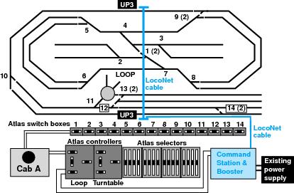
Figure 2-3: Wiring Changes to convert the Santa Fe & Western from DC to DCC
Next, use a decoder equipped locomotive to test the layout with DCC. Finally, test the layout by running as many locos as you plan to use in normal operation at the same time. This is to make sure that the power pack can supply enough current to run as many locos as you want to be able to run. If the power pack shuts down from overheating or overloading or locomotives already running slow down significantly when new locomotives are started, then the load on the power pack is too great. If the load is too great, replace the power pack with a higher output power supply. Conventional power packs were designed to run one train in a conventional block and not several trains in a DCC district. Typically, a power supply used for DCC must be able to output enough power to run more locos than a power supply used for conventional control.
With the exception of the reversing section, the Santa Fe & Western uses what is traditionally called common rail wiring. Every segment of track has its own power connection for one rail which is fed through the related block selector switch. The power to the other rail of that track segment is connected to a common return wire. On the Santa Fe & Western this is an example of whole layout common return, because there is a single common return for the whole layout. This is appropriate for the Santa Fe & Western when the DCC conversion is done because the entire layout will be run by a single booster. The turnouts are not used to route power. In general, if the layout ran properly using conventional control, then by installing DCC as described here, the layout will run properly with DCC.
In this example, the conventional wiring for the two reversing sections, the turntable and the reversing loop remain in place. Either of these sections could be automated with DCC components. Remember the shelf you built back at the beginning of this section? There is room on that shelf for the additional DCC components needed to set up automatic reversing. The point of this installation on the Santa Fe & Western is to use the simplest equipment necessary to do the job properly so that you can become familiar with the basic concepts involved in DCC as easily as possible, so automatic reversing is saved for later.
Using DC and DCC Together On A Layout
On the Santa Fe & Western both of the conventional power packs have been replaced with a single DCC command station/booster to control the trains. In the beginning, not all of your locos will have decoders installed and you may be tempted to replace one of the power packs with DCC and to leave the other DC power pack in place. With this arrangement it is possible to run DCC locos on the track connected to the DCC system and conventional locos in the blocks connected to the DC supply. In theory this arrangement works just fine.
In practice, however, there is a problem when a loco from a district connected to DCC runs into a block controlled by DC or vice versa. Crossing between the DC and DCC systems by accident is very easy to do. When this happens, the loco is bridging between the DCC district and the DC block. The DCC booster may be supplying track power current at up to 10 amps. The DC power supply may be rated for less than 2 amps. When the loco bridges between the two systems, the DCC current may completely overwhelm the DC power supply and may damage the DC supply. This is shown in Figure 2-4.
To protect the DC power supply against damage, wire a 12V DC incandescent light bulb into one of the power output feeds of the DC power supply. This is shown in Figure 2-5. An automobile brake light bulb is suitable for this purpose. When the two systems are bridged together, the bulb will be able to dissipate the excess current and protect the DC power supply.
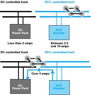
Figure 2-4: Bridging between DC blocks and DCC districts
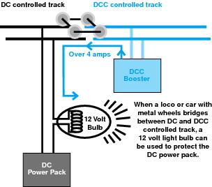
Figure 2-5: Light bulb protecting DC power pack
Layout at a glance
- Scales:
- HO, N