Product Support for: Detection & Signaling -> Block Detector for DS54 (BD1)
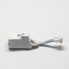
View the Product Page for the BD1The BD1 is a high sensitivity track detector designed for DCC operations and for use with Digitrax DS54 Quad Switch Decoder and LocoNet.
Retired in 2007
6 Articles Found for BD1
Connecting BD1 to a DS54, DS64 and SE8c? The BD1, block occupancy detector (replaced in 2004 by the BD4) was designed as an add-on device, which took advantage of the block occupancy message generating (over the LocoNet) capabilities of the DS54. The BD1 is also compatible, for the same purpose, with the DS64 and SE8c. The following diagrams indicated how to connect the BD1 to the rails, rail power source, and the Digitrax DS54, DS64 and SE8c. Note: The wires that connect the BD1 to the rails and rail power source are characterized as two heavy, uninsulated, and polarity neutral wires.
Q: How can I configure the DS54 for block occupancy detection? A: Any DS54 input can serve as a block occupancy message generator. All that is necessary is to activate a DS54 input with a device that can detect the presence of a train within a specific area/location. The DS54 input can respond to a number of different block occupancy devices including the BD1, BD4, and isolated contacts. The following drawings indicate two different methods (wiring schematics) for the connection of devices to the DS54. The upper drawing Is for isolated contacts and the lower drawing is for BD1 ...
Q: How can the DS54 be configured to control a Flashing Crossing Signal? A: The elements necessary to create a simple function flashing/blinking crossing signal are: a block occupancy detection (trigger) device, an electronic flashing/blinking circuit (DS54) and a crossing signal. The DS54 can accommodate two different types of triggering devices: Digitrax block occupancy devices (BD1 and BD4) and third party block occupancy devices (such as magnets and reed contacts). The following drawings indicate how to connect the two different types of triggering devices, along with the crossing signal, to the DS54. The upper drawing is for the BD1 or ...
The Kelana Jaya Rail Line model is a DCC intense layout, using many Digitrax command control components to achieve the goal of training operators of the actual rail line. The railroad was built in the 1990's and many of the Digitrax devices used for the Kelana Jaya Rail Line model have been superseded with improved units. Components used for the Kelana Jaya layout: 28 Mainline turnouts 11 Yard turnouts 39 Tortoise switch machines 84 Dwarf signals (yellow/green, red/green, red/yellow) 38 Mainline block signals 38 Heavy duty SPDT switch relays Digitrax Components Used for the Kelana Jaya layout: 1 DCS 100 ...
Q: What is the purpose of the single 6-32 screw terminal beside the input connector? A: The 6-32 screw terminal next to the input connector is the -VE Sensor common for the BD1 and BD4 block occupancy detectors. The 6-32 screw terminal next to the input connector should not be mistaken for the standard system ground. The LocoNet connector handles all of the DS54’s system ground needs. Warning: Do Not Connect the 6-32 screw terminal to a house or earth ground (water pipe, electrical ground connection, earth ground stake, etc.) as it may result in damage to the DS54.
The layout uses twenty-eight turnouts on the mainline and an additional eleven turnouts in the yard. Each turnout is powered by a Tortoise slow motion turnout motor. Each of the twenty-eight mainline turnouts has three dwarf signals associated with it. The aspects of the signals are shown below. The indications of the signals are: Green = Proceed Yellow = Proceed with caution Red = Stop Each signal has one head with two LEDs. There are also thirty-eight mainline block signals (red/green) that are controlled by heavy duty single pole double throw relays. This makes a total of 122 signals. Since ...