The Kelana Jaya Rail Line model is a DCC intense layout, using many Digitrax command control components to achieve the goal of training operators of the actual rail line. The railroad was built in the 1990's and many of the Digitrax devices used for the Kelana Jaya Rail Line model have been superseded with improved units.
Components used for the Kelana Jaya layout:
- 28 Mainline turnouts
- 11 Yard turnouts
- 39 Tortoise switch machines
- 84 Dwarf signals (yellow/green, red/green, red/yellow)
- 38 Mainline block signals
- 38 Heavy duty SPDT switch relays
Digitrax Components Used for the Kelana Jaya layout:
- 1 DCS 100 (Super Chief) command station
- 4 DB100+ boosters
- 21 DS54 decoders for turnout control and computer feedback
- 8 BD8 block detector modules
- 3 BD1 block detector modules
- 12 UP3 LocoNet plug-in panels
- 5 DT100 handheld throttles
- 4 Regulated 13.8 VDC 7 amp power supplies
Readers will note that the DS54 stationary decoders have been replaced by the DS64, the BD8 block detector has been replaced by the BDL16, the BD1 block detector has been replaced by the BD4, the UP3 panels have been replaced with the UP5 and the DT100 has been replaced by the DT400 and the UT4 throttles. One net outcome of the improvements is that fewer block detector modules would be needed. Another net outcome is that the throttles are not tetherless, either via infrared or radio control.
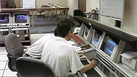
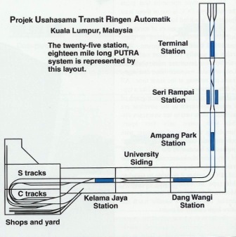
The layout is controlled by a PC attached through LocoNet to a DCS100 Super Chief command station. Five DT100 throttles are used for manual control and the computer runs WinLok DCC software for automated control. The automated control is programmed to duplicate exactly the control system for the PUTRA prototype, modified only for the scaled down distances and the reduced number of stations. The automated control system is used by the supervisors and central control operators for training. It is programmed to simulate emergency conditions such as partial power failure, collision between trains, derailments and accidents involving people. Power is supplied to the layout and boosters by four separate power supplies, each providing regulated 13.8 volts DC supply at 7 amps. The 7 amp (11 amps peak) power supplies can easily handle up to three boosters each. Each booster is protected by a 5 amp circuit breaker. The reversing loop and its reversing section is a 30 inch long section of single track that will never draw more current than is used by a single train. The power requirements for the model were calculated based on 0.3 amps operating current per powered unit so that there is plenty of power to run the trains. Power Distribution The track on the layout is organized into four power districts:
- Mainline west, yard, reversing loop
- Mainline east, DS54 dedicated booster
- Maintenance yard and signal lights
- Reversing Section
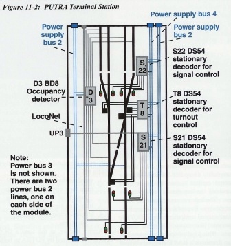
The power bus is a 14 AWG wire harness with modular connectors that allow each section of the layout to be connected electrically. There is a separate power district for turnout control and separate power buses for auxiliary turnout power to the stationary decoders and for the signal light power. These two buses don't carry the DCC signal. The figure below shows the section of the layout which comprises the stub terminal and its associated control, turnout and signal wiring.
Information originally printed as part of The Digitrax Big Book of DCC.
Part 3 of 5