Norcross Southern
The Norcross Southern was a medium sized N-Scale demonstration layout. It was built in the conference room at the old Digitrax production facility, and has since been dismantled. This case study was originally presented as part of the “Digitrax Big Book of DCC” and it has been reproduced here from that text. This study was originally presented as part of three chapters about DCC Installation based on different layouts. The other layouts discussed were the Sante Fe & Western and the Brandywine & Benedictine. It is recommended that you read these studies as well as some of the topics overlap.
Norcross Southern
The next example is a medium sized N scale railroad which was built from the ground up to use DCC. The railroad is called the Norcross Southern. This case study will address the considerations for a new layout of this size and complexity.
Layout Analysis
Figure 4-1 shows the track plan for the layout. The track plan could easily be scaled up to HO size and will fit along two walls of a double garage. The Norcross Southern was built in N scale to fit an L shaped space 11’-6” by 14’-6”. It is intended primarily for DCC display and demonstration purposes, with running trains as its primary emphasis. Since prototype operation is not a consideration here, there is no mainline staging yard, no main yard and no engine facilities. However, the twice around plan does provide five passing sidings so several trains can be run simultaneously and can demonstrate a fully operational signaling system. Also there is sufficient switching to operate way freight or two. A timesaver switching area like that designed by the late John Allen has been built into the shorter leg of the layout. The layout also demonstrates computer assisted switching with car occupancy detection, automated switch control, feedback and automated route selection. In fact the entire layout is designed so that it can be set up to use computer control software, like WinLok, Railroad & Co. or Engine Commander for automated control. It is not necessary to use a computer to run the layout. Normal manual control will be used most of the time, but computer control is an option.
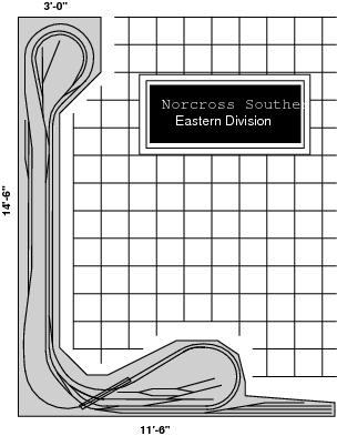
Figure 4-1: Medium sized layout, Norcross Southern track plan
The Norcross Southern shared the room with a conference table and some white boards. To keep the room as clear as possible, the benchwork is cantilevered from the walls. The only legs are installed around each end lobe, just in case someone sits or leans on the layout. The layout is built out of plywood and Masonite. The height of the layout is about 38 inches so that it can be operated and viewed while sitting down. The backdrop is painted on the walls and illumination is provided by track lighting mounted on the ceiling.
When analyzing the layout for DCC, a number of important characteristics must be considered to ensure that operating problems are minimized. Many of these considerations are not unique to a DCC layout and may seem obvious, but as the layouts you build get larger and larger, these considerations become increasingly more important.
First, let’s look at layout power. Sufficient power circuits and outlets must be available in the room for the railroad. The room has one regular double outlet beneath the layout on each of the two walls and a third outlet under the lobe at the end of the long leg of the layout. That is plenty of outlets for the computer, layout power supply and layout lighting. There is also another double outlet in the room for non-railroad use. Track power must be provided to all parts of the layout, so we must be sure that the wires don’t extend so far from any booster that significant voltage drop would occur. Since this layout only measures about 25 feet from one end to the other, there won’t be any worries about voltage drop problems provided an appropriate gauge wire is used to distribute the power to the layout. Since the booster is placed near the “middle,” the wire can easily extend 50 feet in either direction from the booster before we would need to consider increasing the gauge of the wires or adding a second booster. See TABLE4-1 for information on distance and wire size used. When determining how big a power supply will be needed consider how many trains will be run and how much power they need. Since the plan is to run five trains, each powered by two N scale locos with modern high performance can motors and a switcher running on the timesaver, which is about 3.5 amps total operating current. Operating current information can be seen in TABLE 3-1. The addition of locomotive lights and a train of lighted passenger cars will still not bring the operating current over 5.0 amps which is the output of a single DB150 booster. A separate booster will be used to run the turnouts and signals because the total layout current draw is near the current output limit for the booster that will power the trains. A second booster will also add to the reliability of the layout as discussed later.
|
Table 4-1 Typical minimum wire sizes for various run lengths |
||
|
Length |
Current in Amps |
|
|
0-5 |
5-8 |
|
|
0’-30’ |
18awg |
16awg |
|
30’-50’ |
14awg |
12awg |
|
50’-100’ |
12awg |
12awg |
|
Table 3-1 Typical current requirements by scale |
|||
|
Scale |
Stall Current (Amps) |
Operating Current (Amps) |
|
|
Z & N |
0.5 - 2.0 |
0.2 - 0.4 |
|
|
TT & HO |
1.0 - 2.0 |
0.5 - 1.0 |
|
|
S |
2.0 - 3.0 |
1.0 - 2.0 |
|
|
O (2 rail) HD |
8.0 - 12.0 |
3.0- 5.0 |
|
|
O (2 rail) HP |
2.0 - 5.0 |
1.0 - 3.0 |
|
|
O (3 rail) HD |
6.0 - 8.0 |
3.0 - 5.0 |
|
|
O (3 rail) HP |
2.0 - 5.0 |
1.0 - 3.0 |
|
|
G |
3.0 - 6.0 |
1.5 - 3.0 |
|
|
HP = High Performance |
HD = Heavy Duty |
||
The next consideration is how the layout will be controlled by the operators. With a layout of this size and shape all the trains can be seen from anywhere in the room, so there are no limits to the location from which operators can control the layout. The Norcross Southern is set up to be able to use any or all of tethered, radio and infrared throttles available from Digitrax. The seven foot long throttle cords allow the operators to reach entire layout from just two locations. Since they have clear line of sight, only one infrared receiver is necessary. There is nothing in the room which could interfere with the reception and transmission of radio signals so, there should be no problems running radio throttles. Provisions for automated control of all the turnouts will be made, even though all of the turnout motors will not be installed to begin with. Provisions for detectors and signals will also be made; although we won’t get all these going at the start. We need one throttle per operator to run the layout, unless one of those operators is using the computer for control. Since this is a relatively small room, if tethered throttles were used for all operators, we would probably have problems with operators walking into and tangling the throttle cords. Also, enough throttle jacks to plug in five or six throttles at once would have to be added. On the Norcross Southern, the best results will be achieved using mostly wireless infrared or radio throttles so that the operators can follow their trains around the looping track plan without getting in each other’s way.
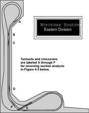
Figure 4-2 Norcross Southern Mainline
Next, examine the track plan to identify any reversing sections. The Norcross Southern has neither a turntable nor a wye, so we are looking for reversing loops. Figure 4-2 shows the simplified track plan with all the spurs and simple double ended sidings along with their turnouts removed. Each of the remaining crossovers is labeled. Figure 4-3 shows this same simplified track plan drawn in a schematic form with the track untangled in a straight line. The crossovers are indicated with the same labels as in Figure 4-2. The direction of travel of a train along the main line is marked with arrowheads. Where the direction of travel past each end of a crossover is in the opposite direction, there is the potential for a reversing section. Upon examination of the layout, we see that there are two reversing loops, one at each end of the layout. This is shown in Figure 4-4. Exactly how to handle these loops will be discussed later, but at the moment we need to acquire the DCC components necessary to control the reversing sections automatically.
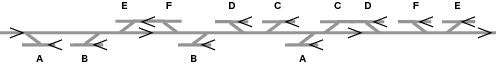
Using the “arrow” method to identify reversing features, we use an arrowhead to show the direction of travel as a train runs along the mainline.
Where a turnout or crossover joins two tracks with arrowheads in opposing directions, a potential reversing feature exits.
Figure 4-3 Norcross Southern Track schematic diagram
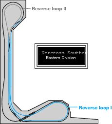
Figure 4-4 Reversing Loops
Figure 4-5 is a diagram of a portion of the schematic showing the rails, rail power feeds, turnouts, turnout power feeds and the LocoNet cable. Figure 4-6 shows the same area as it would be wired for conventional control. Note that there is no LocoNet cable, but look at all those cab control wires and block selector switches. To keep it simple, the diagram shows wiring for only three cabs, not the four or five that would be needed for the Norcross Southern! These two diagrams demonstrate the wiring simplification achieved in the real world by using DCC. From these two diagrams you can see that DCC and analog control need almost exactly the same wiring for power distribution and that this wiring is fairly simple. DCC uses enormously simplified wiring for control when compared with conventional methods.

Figure 4-5: DCC wiring for Norcross Southern
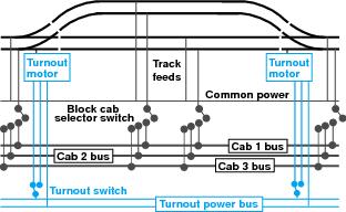
Figure 4-6: Conventional wiring comparison for Norcross Southern
Power Districts
The term power district is one we are going to use a lot as power wiring for DCC layouts is described. A power district is the power wiring and the components and equipment attached to that wiring, driven from a single properly isolated booster. Usually a power district is associated with rails and the trains that run on them. But, a power district may also cover turnout motors or signals and their controls.
There are two main reasons for breaking a layout up into more than one power district. The first reason is operating current limits. A booster can supply a given number of amps. With DCC, the booster must supply current to all the locos under its direct control; that is, all locos in its power district. On a conventional layout, the cab needs only to power the active blocks, usually with only one train in each block. Because DCC makes simultaneous control over multiple trains possible, operators tend to run more trains at once on a DCC layout. With high performance motors and the smaller scales the boosters can usually run all the trains our little heart’s desire, even with five or six operators. But, in the larger scales, or with heavy duty motors, two locos could be the limit for a booster. Also in the larger scales, lighted passenger cars and accessories like smoke units also greatly increase the current draw on the booster. In these cases the best solution is to break the layout up into power districts so that no single booster is overwhelmed by the operating current required to run all the locos, lights and accessories. If a booster becomes overloaded it will automatically shut itself down so no damage will result, but it certainly spoils the enjoyment of operating trains. LocoNet provides communication between the boosters, throttles and command station, so the locos pass seamlessly from one power district to the next. If the turnouts are controlled from the throttles or from the computer, their motors must be connected to the DCC system and driven by it, too. So, to avoid overloading the booster, it is a good idea to use a separate power district for the turnout motor power. If several turnouts were thrown at once, the temporary increase in power load could easily exceed the output of a single booster if it were running both the trains and the turnouts. At best the locos might slow a little and their lights might dim. In the worst case the booster might overload and shut down. Also, it is a good idea to separate the turnout motor power supply from the signal power supply, so that the signals don’t flicker when a turnout is thrown.
The other reason for having more than one power district is to improve operating reliability. Boosters are designed to shut down when a short circuit is detected. This protects both the booster and any equipment on or lying across the tracks. DCC currents can be significantly higher than those encountered with conventional operation. If a large layout were set up with a single booster, running as a single power district, and if an operator caused a short by running through a turnout set the wrong way then the booster shut down the whole railroad. If the turnout control were run from that booster as well, then the turnout control would also shut down and it would not be possible to throw a turnout to correct the short. By breaking the layout up into more than one power district, when a short occurs, it will affect only the power district in which it occurs. It is also much easier to troubleshoot electrical problems in a layout divided into power districts because you can narrow the problem down to a single power district or power district boundary. Both rails must be gapped at the boundary of a power district.
The Norcross Southern layout has four power districts: one for the mainline, one for the timesaver switching area and one each for turnout control and the signal system. A DCS100 command station/booster is used for the mainline district and a DB150 is used for each of the other power districts. Both the DCS100 and the DB150s can supply 5 amps. A booster that supplies 8 amps or even more could also be used. But, since the rails are effectively open un-insulated conductors, at the voltage levels used in model railroads, boosters above 8 amps are not used very often for safety reasons.
Wiring
Each power district that powers the rails is wired as shown in Figure 4-7. The long wires used to carry the power from the booster around the district to the rails are called the power bus. The short wires running from the power bus to the rails are called the track feeds. The approximate operating current for the Norcross Southern is 4.5 amps and the maximum wiring run for the power bus will not exceed 25 feet out and back. TABLE 4-1 shows the recommended wire gauges for power buses for various operating currents and distances. Since the operating current of the layout is near 5 amps, to allow for a modest increase in the future, 16 gauge wire is used for the power bus. The track feeders are kept as short as possible. They are spaced 6 to 10 feet apart along the rails and made from 22 to 24 gauge wire. Digitrax boosters have a safety ground which should be connected to a cold (electrically) metal water pipe or to the third prong earth of the house supply. If the safety ground is connected properly, you won’t fry the system, the cat or innocent bystanders. If you are not sure how to connect the safety ground, by all means, call a professional to handle this important safety precaution.
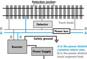
Figure 4-7 : Wiring for a single power district
Figure 4-7 shows the two power bus wires labeled A and B. A is the power district common return and B is the supply wire to the various track segments within the power district. Occupancy detectors are inserted into the track feeder wires from the B side of the power bus and the rails connected to these feeders are single gapped to create detection sections. Each separate power district uses a separate power district common return.
Figure 4-8 shows the wiring for two adjacent power districts. Each of the power districts uses common return wiring, with the power districts double gapped and electrically separated. This wiring method using electrically isolated power districts is called direct home wiring. Direct home wiring is used on the Norcross Southern for a number of reasons.
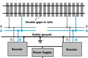
Figure 4-8: Direct home wiring for power districts
With each power district electrically isolated, it is easier to identify wiring problems. It is always possible to isolate a particular problem in a specific power district.
Since there is no whole layout common connection between power districts, current return between power districts is handled by an explicit third wire. This wire is the safety ground.
Each reversing section is handled as just another power district without any special wiring. With direct home wiring you don’t need to rewire steam locos with offset power pick-ups.
With direct home wiring, one power supply can drive multiple boosters. In Figure 4-8 the two boosters share the same power supply. If the total operating current for the layout were 6 amps, each power district could use a 5 amp booster since it would be unlikely for every loco running on the layout to be in the same district at the same time. Both boosters can be provided with power from the same properly protected power supply. This power supply needs to handle just the total layout load, not the total theoretical output of all the devices connected to it.
It is important to note that where two power districts adjoin, both rails must be properly double gapped. It is also important that the power feed for the rails on either side of the gaps come from the same terminal, A or B, of each booster as shown in Figure 4-8. These power district gaps can be tested with a test light with leads or a coin. If the test light comes on, then the polarity across the gap does not match, so the power bus feeds for one district need to be reversed. Place a coin across the gap and if the boosters detect a short across the gap and shut down then, again, current was flowing and the wiring must be changed. In either case, if no current flows, then the two power districts are correctly wired with respect to each other. Make sure that these rail gaps between power districts are filled with epoxy or a piece of other insulating material up to the rail height as shown in Figure 4-9. This prevents the rails from expanding and accidentally causing a short circuit or connecting two power districts together.
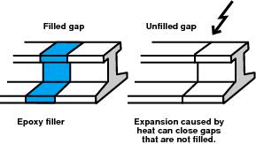
Figure 4-9: Insulated Gaps
Why don’t we use what is traditionally termed whole layout common return wiring for the power districts as shown in Figure 4-10? After all, common rail wiring is familiar to many modelers and is already installed on many existing layouts. Ease of troubleshooting is the most important reason for not using whole layout common return wiring. With all the boosters connected together, it is harder to track down electrical problems. With direct home wiring, electrical problems can be isolated to the specific power district where the problem is located.

Figure 4-10: Whole Layout common rail wiring
Also, because DCC uses alternating current to power the rails, the rail voltage goes from maximum plus to maximum minus each cycle. If a short accidentally occurs at the gap between two powers districts which were wired with opposite polarities or at the gap at the end of a reversing section, the voltage difference across the gap could be twice the track voltage. That could well be over 40 volts in G scale, depending on the way the boosters are connected to the power bus. See Figure 4-11.
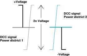
Figure 4-11: Sort across two power districts
With a whole layout common return wire carrying the entire layout current, this wire must be very large, at least 10 gauge, the minimum safe gauge for up to 25 amps. Such wire is more than 1/10th of an inch in diameter and is not easy to handle, install or join.
Reversing Sections
Ever since two rail wiring was developed, controlling reversing sections created by reverse loops, wyes and turntables has been a problem. The problem is that at either the entrance to or the exit from the reversing section, there will be a mismatch in track polarity with these track configurations. If the polarity of two adjacent track sections is not matched, a short circuit occurs; this will prevent continued operation of the train. Once the polarity is matched, operation can continue. Figure 4-12 shows the problem inherent in the track geometry for reversing sections. The problem is the same for both DC and DCC layouts. With both DC and DCC, there are several solutions to this problem: traditional manual reverse control, automatic reversing with traditional relay or auxiliary switch contact control or automatic reversing with an automated reversing device. None of these methods are part of the DCC Standard or RPs but since reversing sections have a major effect on layout wiring and operation, they will be discussed here in relation to DCC.
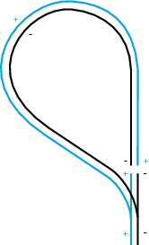
Figure 4-12: Reversing section polarity
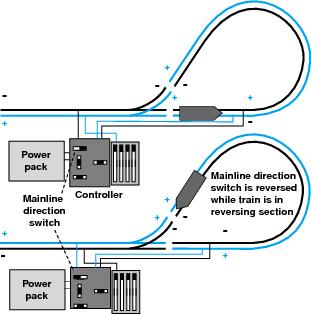
Figure 4-13: Conventional reversing control
Conventional manual reversing control involves using a manual switch to match the track polarity. Relays can also be used to automate reversing sections. One way to solve the problem of mismatched electrical polarities in and isolated reversing section is to use Atlas controllers. The heart of the controller is a double pole double throw (DPDT) switch. If these controllers are wired as Atlas recommends, the DPDT switch is thrown to match the polarity of the reversing section as the loco enters and then the switch is thrown again to reverse the polarity for the mainline before the loco exits the reversing section. This process is shown in Figure 4-13. Using a DPDT is the simplest, and probably most common, way to handle reversing sections. Unfortunately, this method requires that a switch be manually thrown by the operator every time the train is run around the loop. Reversing section control can be automated by using auxiliary switch control contacts and/or relays. Figures 4-14 and 4-15 show two methods of automating a reversing section using these methods. Figure 4-14 shows how an Atlas snap relay is used to control the polarity of a reversing loop using the same control switch as the solenoid turnout motor which controls the entrance to the loop. An Atlas snap relay is a solenoid driven DPDT switch. When the turnout is thrown, the relay is also operated and the polarity of the reversing section matches that of the exit route. Figure 4-15 shows how additional contacts added to a stall motor switch machine can be used to drive a DPDT switch. This switch controls the polarity of the reversing section of a wye. When the turnout is thrown, the track polarity is changed. You can also connect a DPDT switch mechanically to the turnout throw bar so that the switch operates when the turnout is thrown. In this case, the turnout can be operated manually, if desired.
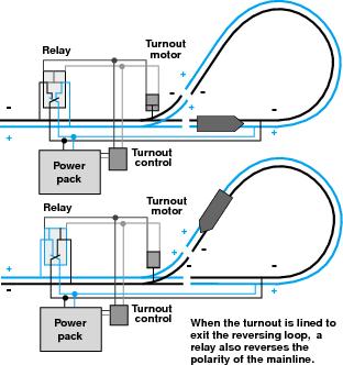
Figure 4-14: Reversing with Atlas snap relay
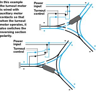
Figure 4-15 : Reversing with auxiliary turnout motor contacts
An automated reversing device (ARD) can be used to solve reversing section track polarity mismatches automatically. Using an ARD is not limited to DCC layouts. Some ARDs are capable of performing automatic reversing for a layout running under either DCC or conventional control.
There are several different types of ARDs designed to work specifically with DCC. One type is the automatic reversing booster (ARB). Even though automatic reversing is not part of the DCC Standard or RPs, the capability is included in some DCC components and is compatible with most DCC systems. To use an ARB, set up the reversing section a separate power district and run it with its own booster configured for automatic reversing. Set up the remainder of the layout as one or more power districts run by one or more regular boosters. Not every booster made by every DCC manufacturer has automatic reversing, so be sure to check with the manufacturer. An ARB works because the power to the rails is actually alternating current and, for a DCC decoder equipped locomotive, the direction of travel is not dependent on the polarity of the rails like with conventional DC control. For a decoder equipped loco to cross the double gaps at the boundary between a power district and a reversing section, the feed from the boosters must match polarity, just as they would between any two conventional blocks as shown in Figure 4-16. When the booster set for auto reversing detects a short in its power district, the booster reverses its output feed before any other booster has time to react. The decoder in the loco is providing DC power to the locomotive’s motor and is not affected by this polarity reversal. This process is shown in Figure 4-17. For example consider the following scenario:
1. The polarity at the gap is matched when the loco enters the reversing section as shown in Figure 4-17a. The loco crosses the gap and continues around the loop.
2. When the loco crosses the gaps to exit the reversing section, a short is detected by both boosters I and II shown in Figure 4-17b.
3. Since booster II is set up for automatic reversing, it reverses its output polarity as soon as it detects the short-circuit. If this corrects the short circuit condition, then booster I no longer has a short circuit to detect and the railroad continues as if nothing has happened. See Figure 4-17c. All this short circuit detection and polarity switching takes place so quickly that it is invisible to the operator.
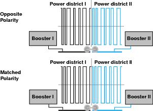
Figure 4-16: DCC phase and polarity
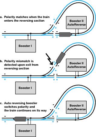
Figure 4-17: Automatic reversing
Of course, you still need to make sure the turnouts at the exit of the reversing section are thrown correctly. If the short circuit detected by the boosters is not corrected by reversing the auto reversing booster’s polarity, then one or both boosters will shut down automatically to protect themselves and the equipment on the track.
Another type of automatic reversing device (ARD) contains sensor and switching components similar to those in an ARB, but does not include the track power supply and amplifier components of a booster. In this case, The reversing sections on the reversing section is double gapped as before but, the auto reversing device intercepts the power output from a regular booster. When power control for both rails goes through a power control device separate from a booster, that is called a power sub-district. This is usually a section of rail driven by a booster, but with its own isolation and/or control systems.
An auto reversing device works just like the ARB when a short is detected. Before the booster it is connected to has time to react, the ARD reverses the power output to its sub-district. If this power output reversal corrects the short circuit condition, the booster never reacts to the short on its own. If the short has some other cause, then the normal booster shut down takes place. Automatic reversing devices which operate like this are available from a number of manufacturers and although the details of operation for each one may be slightly different from what has been described here, their effect is the same.
Yet another type of ARD uses extra gaps cut in the rails to sense the polarity of the approach track before the loco enters the reversing section and as it exits the reversing section. These ARDs match the polarity before any short occurs. This approach requires more complex wiring, and more gaps must be cut in the rails. Also, locos that do not have all wheel pickup may not trigger the ARD. Steam locos with offset pickups will probably need to be rewired if this type of ARD is used. The main advantage of this type of ARD is that the reversing section can be kept as short as the longest group of locos that will be run through the reversing section. This type of ARD can be used to control a reversing section, but it cannot control a turntable.
You probably will not want to run conventional analog locos without decoders on your DCC layout if you are using automatic reversing. This is because the conventional locomotive’s direction of travel will reverse when it sees any reversal in track polarity caused by any auto reversing booster or device in use on the layout.
The reversing sections on the Norcross Southern are wired for automatic reversing using a Digitrax PM4 auto reversing device and a DB150 auto reversing booster.
Because the automatic reversing function is only activated when something tries to enter or exit the reversing section, it is possible to use one automatic reversing device to control more than one reversing section. Everything will work smoothly provided the ARD doesn’t have to resolve two shorts at the same time. The mainline booster will shut down if the ARD is trying to reverse the input to two different reversing sections in opposing polarities because it will see a short. It can’t do both polarities at the same time and it can’t flip-flop back and forth between the two. Figure 4-18 shows how this problem might occur and, as you can see, there is really no way to set up the wiring to allow booster II to handle both locos and reversing sections at the same time. In this situation, the best solution is to add another ARD or control one of the reversing sections conventionally.
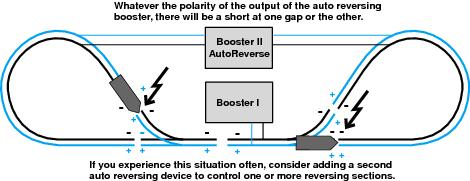
Figure 4-18 : Automatic reversing devices can handle only one gap at a time
Generally speaking, it will take only a brief amount of time for a loco to cross a reversing section boundary. Although, if your train is headed by an ABBBBB E unit, it will take a little longer. In this case the ARD will be busy handling auto reversing for that train until the last wheel of the last unit has cleared the reversing section boundary. The Norcross Southern runs a lot of trains in a relatively small space when it is being used for display. Since the possibility of having more than one automatic reversing event happen at once is likely, the same ARD is not used for both reversing sections. A DB150 booster set up for auto reversing is used to handle one reversing section and one channel of a PM4 power management unit set up as an ARD to handle the other reversing section. The other channels of the PM4 are used to isolate power sub-districts to prevent shorts in those sub-districts from shutting down the entire booster section.
The preceding paragraphs assume that only locomotives at the head of the train will activate the ARD, but there are three other ways in which the gap at one end of a reversing section might be bridged and shorted out if the polarity across the gap doesn’t match. The first way is by mid train locomotives or pushers at the end of the train. For a simple reversing loop, if the locos at the head of the train try to exit the reversing section while the helpers or pushers are trying to enter the reversing section, the ARD cannot match the polarity at both gaps and the boosters will shut down. This is shown in Figure 4-19. Two solutions are possible in this case. One possibility is to make the reversing section longer than the train so that the lead locos are still in the reversing section when the pushers try to enter. Alternately, the reversing section must be short enough so that the lead locos have already left the reversing section when the pushers try to enter. Both solutions are shown in Figure 4-20.
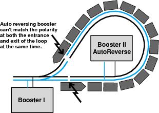
Figure 4-19: Helpers and pushers short out reversing section
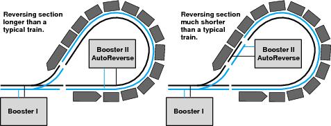
Figure 4-20: Determining reversing section length
Metal wheels will also cause shorts at a gap. In the larger scales, a metal wheel may be able to bridge the insulating gap at the end of a reversing section. If the train is moving, any short is usually so brief that nothing happens. If a problem does occur, it can be fixed by using plastic wheels, by increasing the size of the insulating material so that the wheels cannot bridge the gap or by making the reversing section longer than the longest train.
Trucks with metal wheels and a contact which bridges two axles will also create a short circuit when crossing gaps. This technique is often used by lighted passenger cars, like those made in N scale by Kato, and other cars with power pickup. If there is only one car like this at the end of a train, for example, a lighted caboose or a car equipped with a FRED, then auto reversing works the same way as in the pusher example. The problem can be solved by making the reversing section long enough to hold the whole train or by making it so short that the locos at the front have left the reversing section before the car with power pick-up tries to enter. If the train is made up of lighted passenger cars, then the reversing section must be made longer than the longest passenger train. An example of how this works with passenger trains is shown in Figure 4-21. As you can see, in each case the problem can be solved by making the reversing section longer than the longest train. In general, the best solution for reversing sections is to make them longer than the longest train you plan to run.
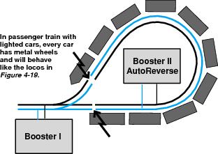
Figure 4-21: Passenger Trains short out reversing section
In the case of using a single ARD to operate two different reversing sections, each reversing section should be occupied for as little time as possible. For this reason, reversing sections should be kept as short as possible. The best compromise involves using an ARD to drive only one reversing section contained in a reversing loop, where the train might run right through the reversing section without stopping. Other reversing sections controlled by the same ARD should be wyes or turntables, which are used less frequently, and were units using them can pause while another train runs though the reversing section in the reversing loop.
Once we decided how to control the reversing sections on the Norcross Southern, the next issue was where to locate them. The main thing to consider is how long the average MU lash-ups will be and how long the trains will be. For the type of operations planned for the Norcross Southern, an ABBA PA loco is probably about average. The reversing section must be longer than any MU lash-up that will be run on the layout. On the Norcross Southern passenger trains with lighted passenger cars will be run so, the reversing sections must be longer than the longest train. Each reversing section will be controlled by its own ARD. Another goal is to keep the track in the reversing section as simple as possible. It is best to avoid a track plan that creates a situation where trains could potentially enter opposite ends of the same reversing section at the same time. This would have the same effect as one train entering and exiting a reversing section simultaneously. Figure 4-22 shows the reversing loop in the shorter leg of the layout. To accommodate the trains, which might contain a four unit N scale PA loco and ten 85 foot long passenger cars, the reversing section should be at least 85 inches long. That is measured from A to C. If two trains try to enter this loop at the same time, they are already headed for a wreck or at least extreme embarrassment. There are no turnouts between A and C, so that keeps it simple. If the passenger cars did not have electrical pickup which bridges the axles, a reversing section from A to B could work. This is only 22 inches long and will just hold the ABBA loco. This is an example of keeping the reversing section as short as possible. By the time a lighted caboose with power pick-up reached the reversing section, the loco in the front of the train would be well out of the reversing section.
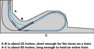
Figure 4-22: Reversing loop I, Norcross Southern
Figures 4-23 and 24 show the other reversing loop. Another possibility for the reversing section is from E to F, encompassing all the trackage in the loop and long enough to hold a complete train. Alternatively, the reversing section could be from E to G, about 180 inches long, in the mainline approach to the loop. This is long enough to hold a complete train on each side of the crossovers which are at the throat of the reversing loop. This is a common solution where back to back reversing loops are formed by a pair of crossovers or a double crossover.
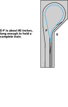
Figure 4-23: Reversing loop II Norcross Southern
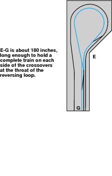
Figure 4-24: Reversing loop II alternative
Turnouts
Now let’s turn to the installation of turnouts on the Norcross Southern. The Santa Fe & Western uses Atlas electrically powered turnouts and Atlas switch control boxes. These control methods were fine for use when the layout was converted to DCC. The Norcross Southern layout is a little more advanced so, automated and remote control of the turnouts will be used.
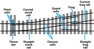
Figure 4-27: Turnout Parts
First let’s consider the turnouts themselves. Figure 4-27 shows and defines the names the various parts of a turnout. There are two main types of turnout designs: power routing and non-power routing or all live. All live turnouts are very straightforward as shown in Figure 4-28. They are called all live because there is live track power to both routes away from the frog at all times, regardless of the setting of the point rails. Jumper wires connect the straight stock rail with the curved frog rail and the curved stock rail with the straight frog rail. Jumpers are also usually provided to power the point rails from the adjacent stock rail. Some all live turnouts rely on mechanical contact between the point rail and the stock rail to provide power to the point rail. When using DCC, don’t rely on this mechanical contact to provide power (and the DCC signal along with it) to the point and closure rails. A mechanical contact is too easily disrupted with dirt and oxidation. The two point rails in an all live turnout are insulated from one another. The two frog rails are also insulated from one another. The point rails are connected by an insulated throw bar. The frog rails can be insulated in several ways. The simplest way of insulating the frog rails is to use an insulated frog made of plastic. This is the most common method for sectional track turnouts. Other turnouts use a non-powered metal frog. In any case, any turnout which uses a dead non-powered frog has a short dead spot in the center of the turnout. This may result in a loco stalling as it passes through the turnout when it reaches the dead spot. The Peco Insulfrog® turnout has a thin insulating strip between the frog rails. Figure 4-29 shows various frog insulation methods. All live turnouts provide power to all rails all the time and the polarity of any rail does not change when the turnout is thrown as shown in Figure 4-28. With the exception of the dead spot in the frog, all live turnouts with jumpers to the point rails are suitable for DCC use and no special additional wiring or gapping is required.
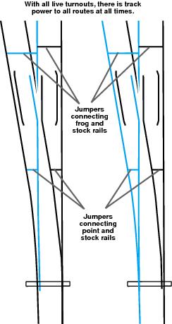
Figure 4-28: All live turnouts
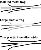
Figure 4-29: Frog insulation methods
Power routing turnouts are both simpler and more complex. They are simpler because the two frog rails meet and are not insulated, the point rails are also connected together and may be connected to the frog. These connections are shown in Figure 4-30. This means that there is a continuous electrical path through the turnout from the point rails through the frog to the frog rails. The point rails can be powered by mechanical contact with the stock rails or by separate contacts associated with the throw bar or the switch machine. Again, mechanical contacts are easily disrupted with dirt and oxidation, so they are not recommended. Power routing turnouts are more complex because of the way the polarity of the rails changes as the turnout is thrown. Figure 4-31 shows what happens when turnouts form a crossover. Unless the turnouts are gapped as shown in Figure 4-32, there will be a short. Power routing is used in Peco Electrofrog®, Shinohara, Micro Engineering and most hand laid turnouts. Power routing turnouts have the benefit of a continuous electrical path through the frog, but require adding extra gaps to prevent electrical problems. Aside from the advantage of the powered frog, in a conventional layout, the main advantage of power routing turnouts is that they can be used to control power to the tracks they are lined for, thus reducing the amount of control wiring needed.
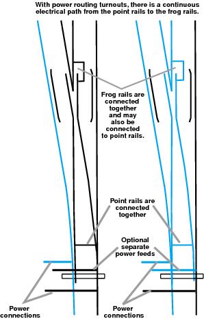
Figure 4-30: Power routing turnouts
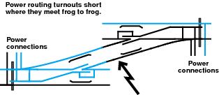
Figure 4-31: Crossover
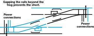
Figure 4-32: Gapped Crossover
With conventional control the wiring for a yard for use by multiple locos simultaneously can be quite complex, so this shortcut with power routing turnouts is worthwhile. With DCC, almost every track segment is powered with its own track feed and it is very easy to control several locos in a single yard. All this means that if power routing turnouts are used with DCC, they must be gapped properly. The safest way to do this is to follow the rules used by most modular railroad clubs. Double gap the turnouts on both rails at the exit from the frog and feed the power from the point rail or toe end. The gaps at the frog end should be kept as close to the frog as reasonable so that locos are not likely to be accidentally parked across the gap.
Carefully gapped power routing turnouts have a subtle advantage for DCC use. If a loco approaches a power routing turnout from the frog end and the turnout is thrown against the loco, a short will occur, the booster will shut down and the loco will stop. If the turnout power and control are supplied from a separate power district, the turnout can still be thrown because that booster will not have shut down, the short will be corrected, the booster running the track will re-activate and the train will continue to run. On the other hand, if a loco approaches from the frog end of an all live turnout and it is thrown against the loco, the loco will not stop. In the larger scales the weight of the equipment may be sufficient to operate the turnout as a spring switch. In the smaller scales you will probably get a derailment. I belong to a modular railroad club that uses DCC and shorts caused by running an incorrectly thrown turnout are pretty common, occurring about once an hour or so at a public show. The short can be corrected in a couple of seconds. A derailment is a lot more embarrassing and takes a lot longer to clear up. If you are going to run a small or medium sized layout primarily by yourself or with a few experienced operators, then pre-built all live turnouts are best. They are easier to install and, if you keep them set for the correct route, you won’t have any problems. In other circumstances, especially with inexperienced operators, power routing turnouts are definitely a better choice.
Any layout using occupancy or transponder detectors, with or without working signals, needs to have gaps cut for the detection sections. Many of these gaps will be near turnouts, so the advantage that all live turnouts have is the reduction of the number of gaps needed for both turnouts and detection is reduced. Power routing or all live turnouts make no difference in the way reversing functions are controlled. For the Norcross Southern power routing turnouts were chosen to minimize the possibility of derailments while running the layout and because occupancy and transponder detectors will be used.
Turnouts using center third rail pickup are shown in Figure 4-33. The stock rails always have the same polarity so there are no electrical problems. These turnouts have the same characteristics as all live turnouts. Whatever type of turnout is used, there will be mechanical concerns. Make sure that there is enough clearance between the backs of the metal wheels, if used, and the powered point rails of opposite polarity. If not, intermittent shorts or electrical arcs may occur which can damage the rails and the wheels. The clearance should be checked with an NMRA Standards gauge. The wheel tread and flanges should also be checked. In reality, enough clearance is whatever works. In most cases you will be able to cure the problem by using clear nail polish, or some similar insulator, on the sides ofthe offending rails.
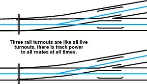
Figure 4-33: Three Rail turnouts
Turnout Control
Let’s look at the control methods available for turnouts. Since this layout is used for demonstrating DCC technology, stationary decoders are used for turnout control. In a small layout it is possible to draw turnout motor power from the power district that also supplies the track. However, the current used by the switch motors counts against the operating current of the booster. On the Norcross Southern there is not much power to spare from the booster that will run the trains. Another consideration is that if there were a derailment and the booster were to shut down, then the turnout control would be shut down as well. For these reasons, the turnout control for the Norcross Southern is handled by a separate power district.
There are two main types of turnout motors: solenoid and slow motion. In addition, there are two types of solenoid motors: three wire and two wire. Three wire solenoid motors have a common power wire, a separate control wire for each of the two turnout positions and they can be set up to use AC power to operate. This type of motor is common for sectional track and has been used since the invention of electrically controlled turnouts. Two wire solenoid motors use DC power and the direction of current flow through the solenoid determines the direction in which the switch operates. Two wire solenoid motors are used in Kato and LGB turnouts and are sometimes called bipolar turnout motors. Figure 4-34 shows how these two types of solenoid motors work. A solenoid motor requires power only when it is changing state although, at that time its power draw is quite high.
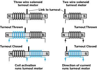
Figure 4-34: Solenoid turnout motors
The slow motion, or stall motor, is also a DC device where the direction of current flow determines the direction of operation. Slow motion turnouts require steady current all the time and provide continuous pressure to keep the turnout locked. A slow motion motor uses less power as it operates than a solenoid does. This continuous current draw is usually about 10-20 milliamps per motor. Although we are discussing turnout motors here, this steady current could be used to drive other types of motors, too. This will be discussed in more detail later.
Digitrax stationary decoders have the necessary outputs to drive both solenoid and slow motion turnout motors. On the Norcross Southern, both slow motion and three wire solenoid motors are used. Stationary decoders used to control turnouts can be much larger than mobile decoders because they don’t have to fit into confined spaces. To reduce the manufacturing costs, stationary decoders are often built with multiple units on a single board and are able to control two, four, six, eight or more turnouts individually.
Mobile decoders receive their input from the command station only via the booster through the power on the rails, and output to the motor and the function leads. Stationary decoders can receive input from the command station through a connection to the rails in the same way, but they often have separate input leads as well. The input leads allow for control of the stationary decoder directly from a fascia mounted switch, just like conventional control. The input could also be triggered by an occupancy detector or a simple logic device connected to another stationary decoder. Since all of these devices are connected to a booster via LocoNet, there is a whole range of ways to control stationary decoders. A fascia mounted switch, a throttle, a logic device or a separate dispatching panel connected to LocoNet or a computer can be used.
Figure 4-35 shows a stationary decoder attached to each type of turnout motor using the simplest installation. The power leads are the same as for a conventional installation, but note the absence of control wires.
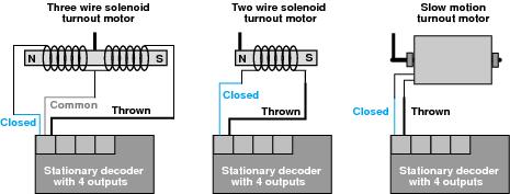
Figure 4-35: Simple stationary decoder control of turnout motors.
Figure 4-36 shows how the operating speed of the slow motion turnout motor can be either slowed down or sped up. The resistors shown must be able to handle ½ watt of power. A resistance value of about 1k ohm is the about right to speed motors up. Test this with several values in your specific circumstances to decide the best speed for your layout.
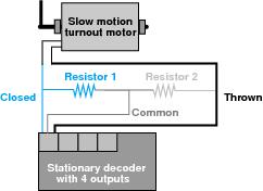
Figure 4-36: Changing slow motion motor speed
The power feed to the stationary decoder could come from track power, but the Norcross Southern uses a separate booster and a separate power bus, so accessory power feeds of similar wire gauge to track feeds from the power bus to the stationary decoder are used.
The two decoder output leads are described as thrown and closed. In railroad terms, closed is usually straight through and thrown is usually the diverging route. You can wire your turnouts to be controlled in this way or you could wire them so that closed is the mainline, normal position and thrown is the secondary, alternate route. That way you can tell your operators to leave turnouts in the closed position when they have finished with them, regardless of their actual state.
If there is a crossover or a double crossover, all the turnouts in the crossover can be controlled with a single stationary decoder when slow motion motors are used. However, when two or more turnout motors are run from a single stationary decoder an auxiliary power supply will probably be needed to provide enough power. This external power supply is 12-16 volts AC for Digitrax decoders and moves the power load off the booster input feed. Because of the high current draw, the stationary decoder output can drive only a single solenoid motor, even with the auxiliary power supply.
The command station can query the stationary decoder and determine the present state of the decoder’s outputs; that is, whether the decoder thinks that the turnout is thrown or closed. This information can be used to drive lights, signals, a dispatcher’s panel or other stationary decoders. This is not feedback. The decoder tells the command station the last state that it sent to the turnout. It cannot tell whether the turnout actually moved to that position or whether it is jammed.
The stationary decoder also has two sensor input leads that can be used to provide either positive or exact feedback for the turnout’s position. These sensors can determine the mechanical state of the turnout. To get positive feedback, add a micro-switch connected to the turnout linkage or to the throw bar. The switch is also connected to one of the decoder input leads and the common power. This arrangement is shown in Figure 4-37a. When the switch S1 is closed, the turnout is closed. When S1 is open, the turnout is not closed. With this arrangement, you can be sure that the turnout is closed. The only drawback is that not closed is not the same as thrown. In this situation, the turnout may be jammed halfway. If you absolutely, positively, must know the exact position of the turnout, both input leads must be used to wire the turnout for exact feedback. This is shown in Figure 4-37b. In this case two switches are installed. If S1 is closed, then the turnout is closed; if S2 is closed, then the turnout is thrown. If both switches are open, then the turnout has jammed in between. If both switches are closed, then the turnout linkage or throw bar may have broken. For most model railroaders the decoder status is probably satisfactory, but positive or exact feedback may be useful for hidden trackage or staging yards. Positive or exact feedback can also be useful if you use a dispatcher’s panel, computer control or when train crews insist on changing power controlled turnouts manually. When using positive feedback the other decoder input lead can be used to control the turnout from a switch mounted on the fascia. Since exact feedback uses both decoder input leads, a second stationary decoder would be necessary to drive the turnout motor from the fascia, unless such a switch were to bypass the decoder completely. The feedback from one turnout could be hard-wired to operate the inputs of other stationary decoders to activate other turnouts, providing rigid interlocking. The same effect can be achieved by programming a group of decoders to work together for this purpose. Since the decoder programming can be changed as needed, this is much more flexible than hard-wiring.
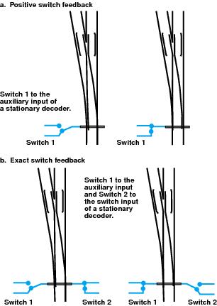
Figure 4-37: Turnout Feedback.
Norcross Southern Timesaver
Let’s discuss the wiring and control of the timesaver switching district that is part of the Norcross Southern layout. The timesaver is set up as a separate power district with its own booster. Figure 5-12 shows the track plan for that power district. Every section of trackage has its own power feed through its own occupancy detector. A stationary decoder controls every set of turnouts. There are six turnouts numbered 1 through 6, but 1, 2 and 3 are ganged together so that they don’t operate independently. When 1 is closed; 2 must also be closed. When 2 is thrown; 3 must be closed. Turnouts 4 and 5 are also ganged together. All the turnouts used are all live turnouts. This means that a separate power feed does not need to be provided for every single piece of track. It also reduces the number of gaps that must be cut. If power routing turnouts were used, double gaps would be needed between turnouts 1 and 2, 2 and 3, and 4 and 5, where the turnouts meet frog to frog. Figure 5-13 shows how the timesaver is gapped and wired. The track is divided into seven detection sections, A through G, and there are three detection sections for turnouts, H through J. The detection sections A through G are installed so that cars can be detected at the various industry locations. With computer control, the computer can work out how to access unoccupied industry tracks when there are some cars already present in the switching district. Each detection section is connected to its own detector. Each of the three turnout groups is set up as a detection section to prevent throwing a turnout if there is a car or loco fouling any of the turnouts.
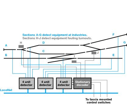
Figure 5-13: Timesaver switching district
Since everything is close together in the switching district, devices with multiple detectors packaged together are an excellent choice. Three four-unit, two eight-unit or one sixteen-unit detector package will be much easier to install and less expensive than eleven individual detectors. Figure 5-13 shows three four-unit detectors.
Figure 5-13: Timesaver wiring.
Each of the turnout detection sections is connected to a stationary decoder. Figure 5-13 shows a stationary decoder with multiple sets of inputs and outputs. Each group of decoder driven turnouts is fitted with a fascia mounted momentary contact actuating switch so that these turnouts can be controlled both from the fascia and the hand-held throttle. The decoders that drive the turnouts need to be provided with a 16 volt AC auxiliary power supply. Each decoder is connected to the power bus of the turnout control power district. The detectors are connected to the timesaver switching district power bus. You could build the timesaver using only one power district but, because of the likelihood of derailments and shorts, the track and the turnouts should be separate sub-districts. Each of these sub-districts should be protected by its own fast-acting isolation device or circuit breaker so that a track short doesn’t disable the turnout control. The decoders and detectors are also connected to LocoNet.
With this arrangement, the timesaver is effectively a completely separate layout with its own detection and control. All the freight cars used on the timesaver will be outfitted with resistor wheel sets so that all of them will trigger the occupancy detectors. If transponders are installed in all of the freight cars used on the timesaver, then the transponder detectors could be used instead. If transponders are installed in the freight cars, transponder detectors can tell which cars are at what industries.
The Norcross Southern is located in a conference room that has a digital clock with a timing capability so that the operators can compete against each other and the clock while solving switching puzzles. The switcher used for the timesaver has a full function decoder with directional lighting so that when it is sitting still, the operator can tell which way it will to move when power is applied to the throttle. Because the Norcross Southern is N scale and the loco is so small, eventually we plan to mount a stationary sound system under the layout with much larger speakers than could be installed in a locomotive. This sound system will provide realistic sound effects. The eye will fool the ear into associating the sounds with the moving loco. Since the switchers are fitted with decoders with integrated transponders, the information sent to the transponder detectors could even be used for a sound system mounted under the layout so that the sound produced matches the type of loco on the timesaver, be it EMD, GE, Alco or Fairbanks-Morse.