The Interstate Railroad Dorchester & Dixiana Branch
Case Study - Interstate Railroad Dorchester & Dixiana Branch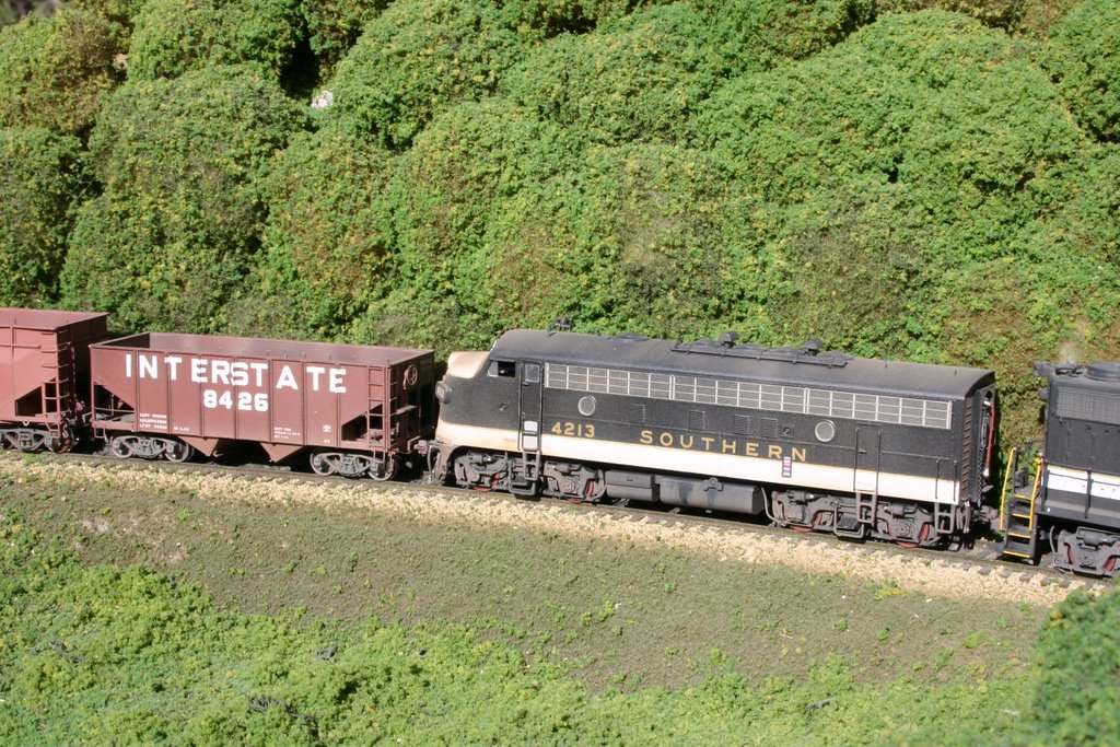
Background
The Interstate Railroad Dorchester & Dixiana Branch is a medium-sized HO-scale layout designed to capture Appalachian coal-hauling operations in southwestern Virginia in the late ‘60s and early ‘70s. The layout (still under construction) was designed with a human factors engineer’s eye for intuitive operation which greatly affected which DCC components were chosen and how they are employed.
The Prototype
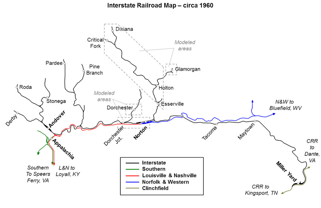
The 88-mile long Interstate Railroad was a coal-hauling short line that operated in extreme southwestern Virginia. Despite its name, the Interstate’s rails never left Virginia. The Interstate had three main things going for it: 1) access to high-quality coal seams, 2) a large hopper fleet, and 3) great connections. The Interstate’s mainline ran from their small yard at Andover to its connection with the Clinchfield Railroad at Miller Yard. Along the way, the Interstate interchanged with the Southern Railway, the Louisville & Nashville, and the Norfolk & Western. Several branches into the coal fields ventured north from the mainline, and Interstate coal flowed to all connecting roads. The long distance between the coal tipples and the offline destinations for the coal necessitated a large fleet of hoppers to keep the tipples supplied with cars. Many years, the “per diem” these cars earned while off the Interstate allowed the railroad to show a profit despite operating losses on its own rails. While the Interstate’s business was hauling black diamonds, it also handled a fair bit of non-coal bridge traffic between the L&N at Dorchester Jct. and the Clinchfield at Miller Yard.
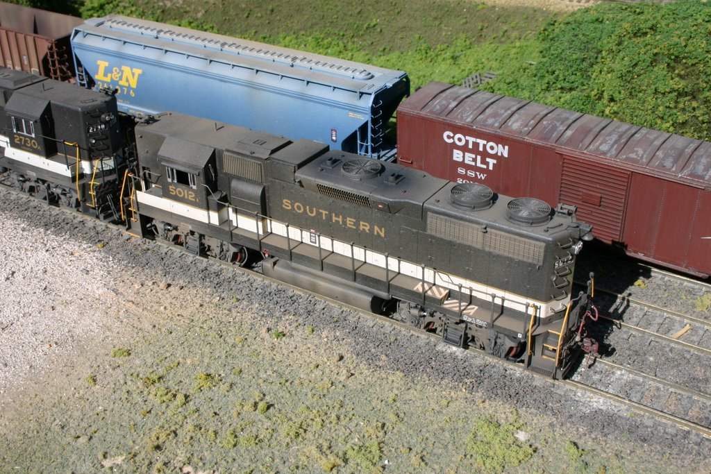
In 1960, the Interstate was put up for sale, and the Southern Railway barely outbid the L&N to acquire the road. The Interstate’s colorful cream, orange and gray RS3s continued to work the line until the Southern took over operations in 1965 and replaced the RS3s with worn-out Southern F-units which lasted until 1969 when GP38s and other power more suitable to the coal fields was introduced. The Southern continued to operate the Interstate independently until the Norfolk Southern era when it was merged into the adjacent Pocahontas Division of the N&W. Coal continues to flow from Interstate rails today.
The Model Railroad
The Interstate Railroad Dorchester & Dixiana Branch is designed to faithfully model the operations of three Interstate coal branches (Dixiana Branch, Glamorgan Branch and Dorchester Branch) and a portion of the mainline between Dorchester Jct. and Norton, Virginia. The model railroad interchanges with the L&N at Dorchester Jct. and the N&W at Norton. Staging is used to represent the main Interstate yard at Andover and the connection with the Clinchfield at Miller Yard. The early Southern era was chosen to model the dilapidated F-units and GP38s side-by-side hauling large modern Southern 100-ton hoppers and the remains of the Interstate’s fleet of 50-ton hoppers. Thanks to the wealth of information in the excellent series of books on the Interstate by Ed and Hugh Wolfe, the prototype operations for working each prototype tipple, interchange and industry have been captured in great detail. The layout was designed as close to switch-for-switch with the prototype as possible so it can be operated just like the real thing using the great reference material available.
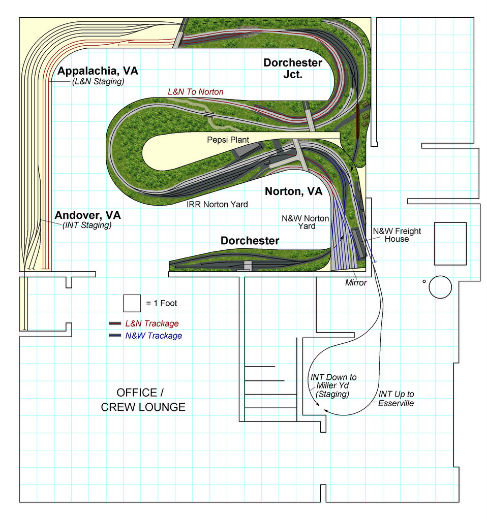
| Lower Deck |
|
|
| Upper Deck |
|
|
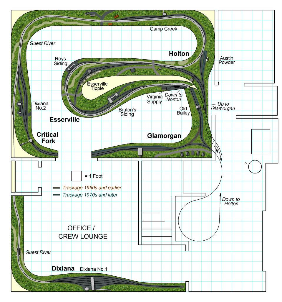
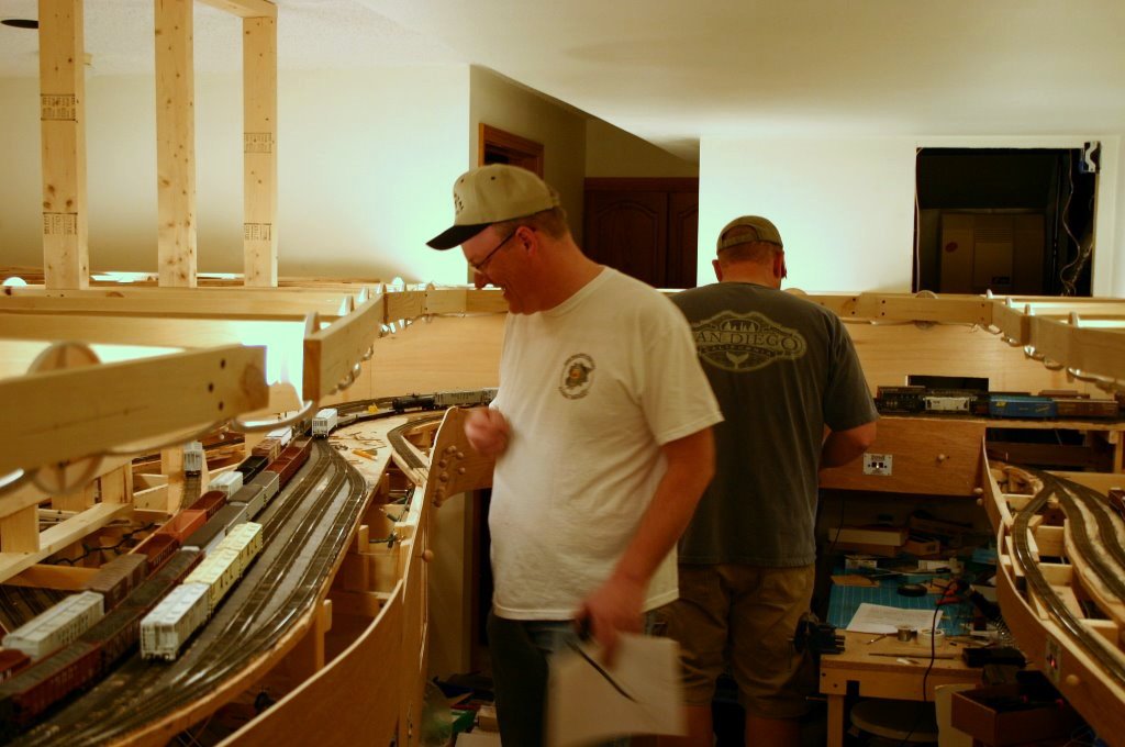
The overall layout has a 21’ x 28’ footprint, but most of it resides in a 15’ x 20’ basement room. The layout is double-decked with the mainline occupying the lower deck and the Dixiana and Glamorgan Branches and their nine coal tipples occupying the upper deck. The mainline is point-to-point with staging at either end. To capture all the tipple and track orientations and wyes prototypically, the branches duck in-and-out of the backdrop in numerous places. The layout is designed for walk-around operations with generous aisles and fascia-mounted turnout controls.
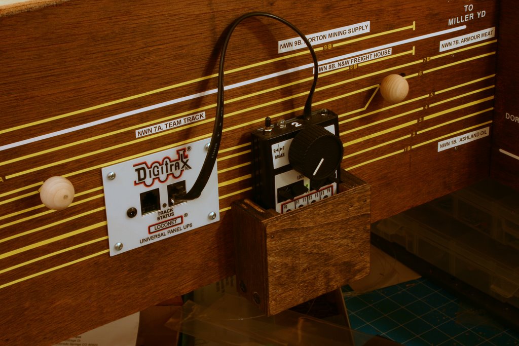
All visible track and switches are handlaid to allow free-flowing track arrangments typical of the coalfields (and to learn and enjoy a somewhat dying art). All turnouts are controlled with simple knobs on the fascia mechanically linked to a DPDT slide switch under the turnout. The DPDT switch serves to lock the turnout when thrown and allows easy power routing to the frog. The track diagram is drawn on the fascia, and the switch knobs are lined up with the diagram to aid operators in throwing the right switches.
Goals for the Layout
- Focus on switching and laid-back branch operations
- Model the real railroad faithfully enough to give operators the same challenges the prototype had
- No dispatcher needed
- Incorporate the L&N and N&W as working interchanges
- Simple, intuitive controls and instructions to allow even novice operators to have fun
DCC Choices
This layout was designed with DCC in mind. The real Interstate Railroad had manually operated switches and was not signaled, so the model railroad follows this practice. Additionally, there isn’t any need to make or break consists during a session as all trains originate and terminate in staging. This greatly simplified the requirements of the DCC system.
After looking at several systems, Digitrax was chosen primarily because of the simplicity of the UT4 throttles and the freedom of radio operation. When the layout was ready for DCC, duplex radio had just been released, so the UT4D throttles and a UR92 were selected. A second-hand Chief system with a DT100 throttle was initially used for the command station. A Zephyr was purchased later to allow the youngest operator (then 5 years old) to easily run trains. Although considered a “starter system,” it turns out the Zephyr was powerful enough to be used as the command station for the entire layout. Because of the expandability of Digitrax through LocoNet and the compatibility of Digitrax products, the simple-to-use Zephyr had no problems being the brains of a rather large, radio equipped layout. The DCS100 was set up as a booster to augment the Zephyr’s power to the tracks. The only limitation of the Zephyr which was not compatible with the final layout design was the limited number of locomotive slots. However, when Digitrax released the Zephyr Xtra, the 20 slots available in the Xtra was more than adequate to run the layout in its final form. A DCS51 soon replaced the DCS50 as the command station (the original Zephyr will eventually be employed as a booster for one of the upper-level branches).
Even though the layout was designed with radio control in mind, several UP5 panels were mounted on the lower deck fascia at increments of 8-10 feet to allow for wired operation if needed. The latest Digitrax addition to the layout is a PR3 which interfaces with a laptop running JMRI. JMRI and the PR3 are used to program locomotives and to manage the LocoNet fast clock. The laptop is also used to control the layout lighting via X10 dimmers.
DCC tips and tricks
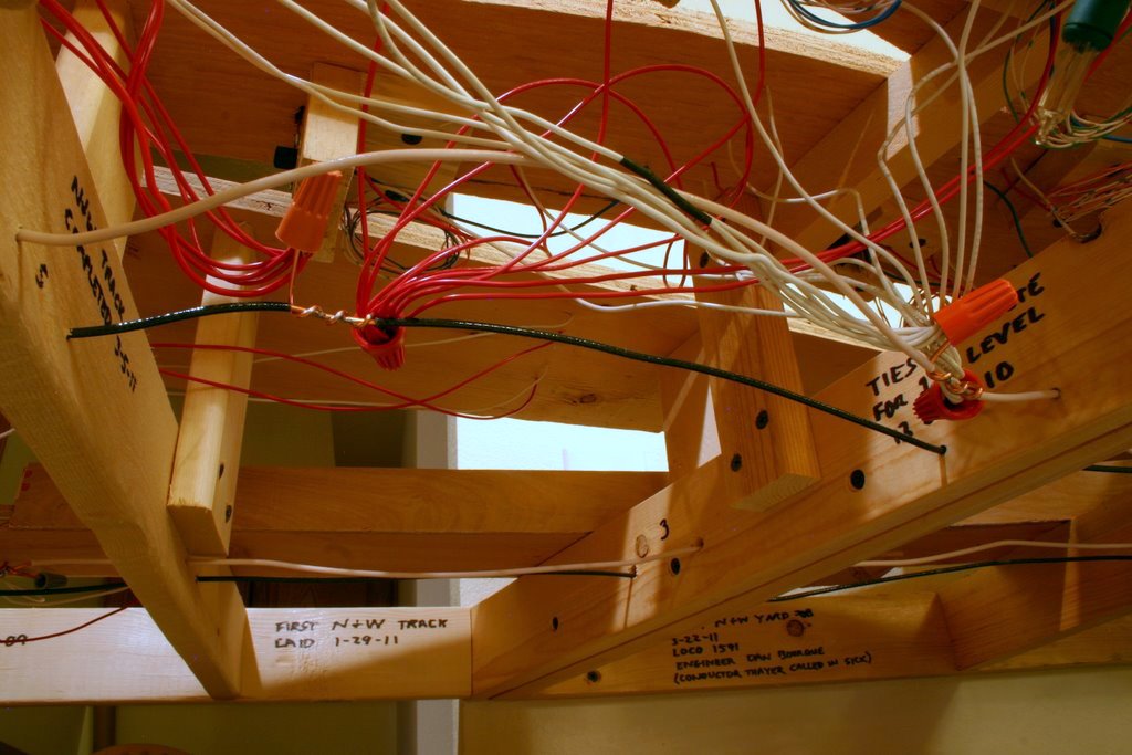
- Lots of Blocks. Even though no additional circuit breaker unit (e.g. PM42) is currently used, the layout is still broken into several small blocks electrically. Each block is electrically isolated and has its own bus made from 14-guage Romex (copper household wiring) to minimize voltage drop over distance. While the blocks are currently tied together at the booster, it will be easy to separate them if operation demonstrates additional power management is needed. The theory: it’s a whole lot easier to tie two blocks together than it is to turn one block into two later.
- Wiring. Handlaid track requires a lot of feeder wires. A single switch requires up to 8 feeders to power all the rails and the frog. To accommodate all these feeders in a manner that’s flexible and easy to troubleshoot, the layout uses various sizes of wire nuts to connect the feeders to the bus. Every 2-3 feet, a small portion of insulation is stripped off the 14-guage bus, and a small length of bare 14-guage copper wire is wrapped around the bus 3-4 times and soldered leaving two “pigtails” at either end for attaching wire nuts. Offsetting pigtails from the two bus wires by several inches decreases the risk of a short.
- Logical Wiring Diagram. If your LocoNet has a lot of devices attached, you may sometimes look under your layout and wonder "now where does that cable go?” It’s
always useful to have an up-to-date diagram of how the LocoNet and DCC components are connected. Your favorite presentation-building software provides an easy way to build wiring diagrams. Besides LocoNet connections, it’s also helpful to include things like power supply locations and ground wire connections to aid in troubleshooting.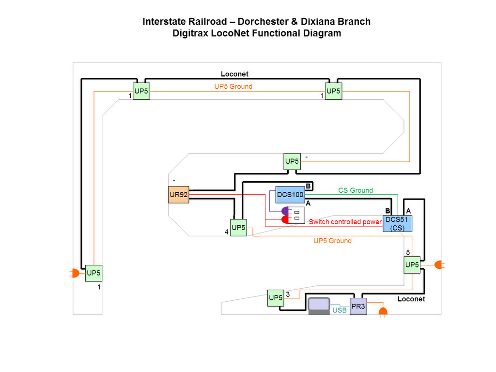
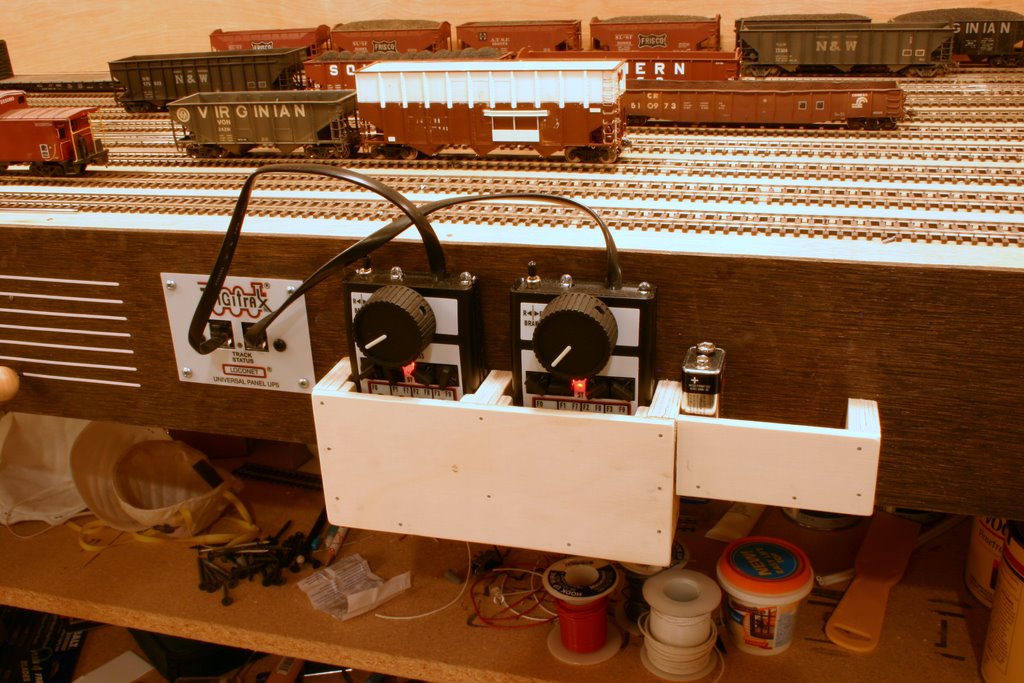
- Throttle Pockets. The layout uses simple throttle pockets for UT4s made from ½” and ¼” plywood. The pockets are 1 ½” deep to protect the knobs from stray pockets or arms that might grab them. Small strips of ¼” ply are used on the sides toward the front of the pocket to keep the UT4s snugly against the back of the pocket and to keep the buttons from scraping against the front of the pocket. There are several of these pockets around the layout in both single and double versions, and one even has a storage bin for 9V batteries. They are all placed within a few inches of a UP5 to make sure the UT4Ds can be plugged in when not in use to save battery life.
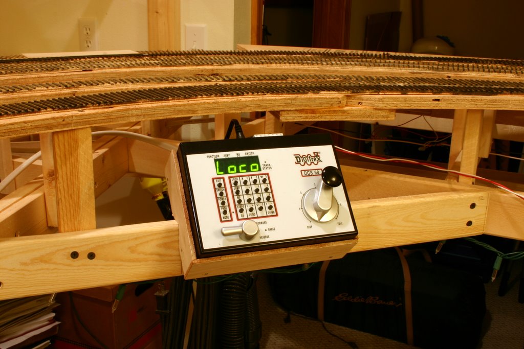
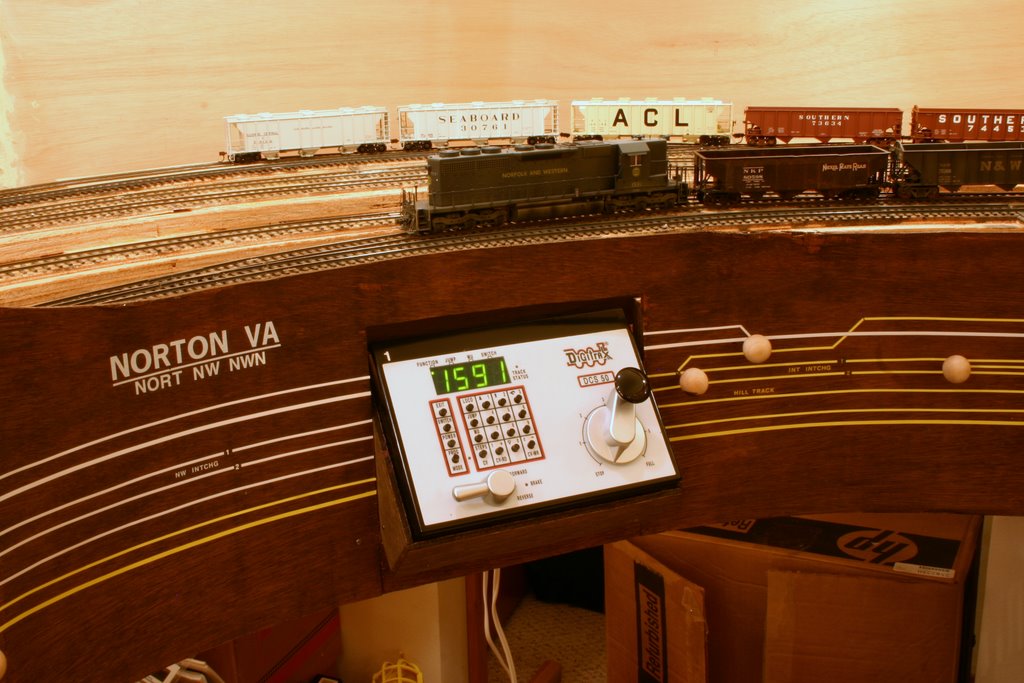
- Fascia Mounted Zephyr. The Zephyr, as the command station for the entire layout, needed to be accessible without being in the way. The logical place for it to reside on the layout was Norton where the N&W basically forms its own 6-foot-long switching layout and can easily be operated from a stationary throttle. Rather than set the Zephyr under the layout, it was instead mounted semi-recessed into the fascia. A simple box just large enough to hold the Zephyr snugly was built out of ½” and ¼” plywood, and notches were cut at 45-degree angles on the sides to allow it to mount to the benchwork at an angle. The fascia was cut to fit around the Zephyr, and between the recess and angle, the unit only sticks out 2 ¼” from the fascia which keeps it from taking up valuable aisle space. The result is pleasing to the eye, easy to use, and hides and protects the wiring in the back of the Zephyr.
- Handy Hooks. To keep all of the LocoNet wires and UP5 grounding wires tucked up under the layout, small hooks are installed behind the front fascia about every 12”. By using hooks instead of drilling holes through the benchwork, the wires can be easily taken down, swapped out, rearranged and replaced.
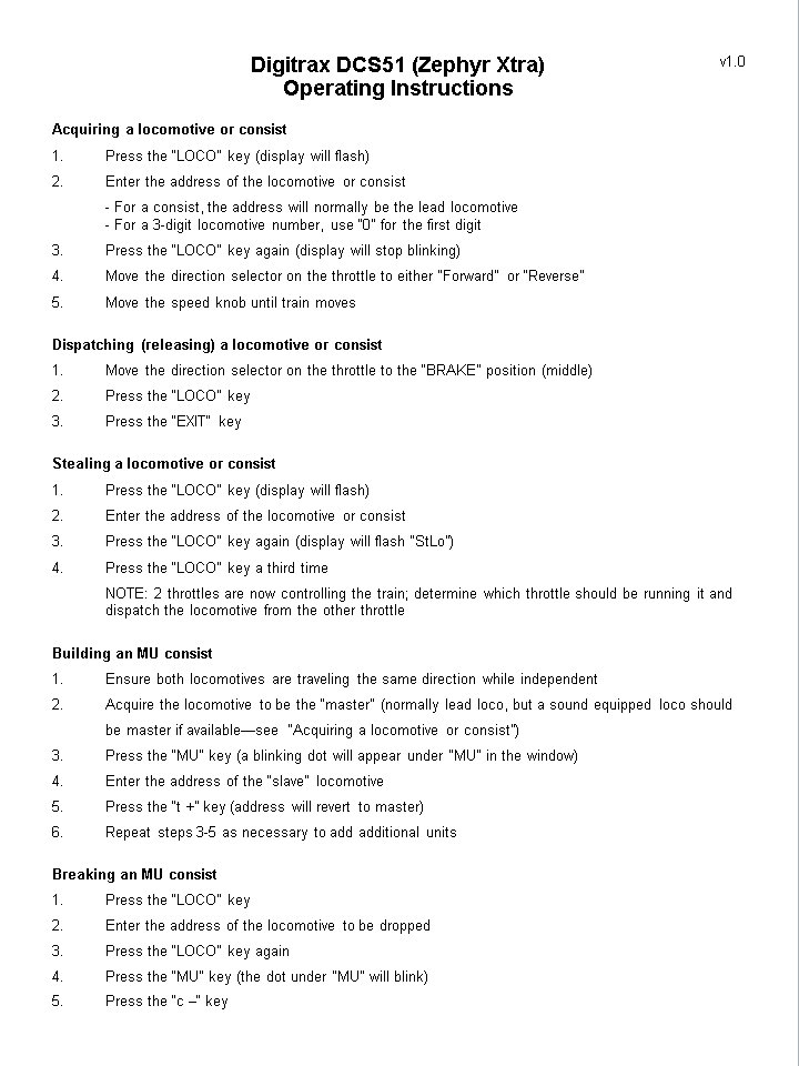
- Cheat sheets. While Digitrax’s manuals are generally easy to understand and thorough, layout crews usually need only a fraction of the information to operate their trains effectively. Simple, one-page operating instructions with the most common procedures were built for each throttle type. The instruction sheet for the UT4Ds has basic procedures for acquiring a locomotive, dispatching a locomotive, stealing a locomotive and loss of radio control. The Zephyr Xtra instructions include procedures for acquiring, dispatching and stealing locomotives and also simple procedures for building and breaking consists. On the back is a list of DCS51 messages and their meaning. These sheets are kept in a well-labeled binder under the layout, and miniature versions are hung from hooks under the throttle pockets and Zephyr housing for easy reference.
While the Interstate Railroad Dorchester & Dixiana Branch has already hosted several operating sessions with as many as 4 operators, the layout is far from complete. As more of the layout is built, it is almost certain it will take advantage of new Digitrax advances and products.
Layout at a glance
- Submitted By:
- Dan Bourque
- Scale:
- HO
- Era Modeled:
- 1960's - 1970's