I am now constructing an N-Scale layout with Digitrax DCC system.
I know SE8C and two-heads signal mast supplied by your company are applicable for a entry signal mast for the both of main and siding (branch) lines.
However, I don't know how the signal mast is used in the case of "more than two" siding lines.
For example, the next picture was taken in Powder River Basin (Converse Jct.) in Wyoming State. TS, Japan
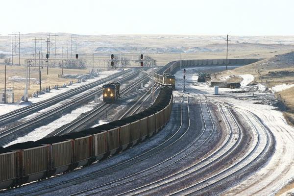
In this picture, some two-heads signal (mast) can be seen.
In every signal mast, the top signal head will be for a main line.
But, I don't know how "a" lower signal head of each mast is assigned for "more than two" diverging routes.
Let's look at the photo that you cite.
There is a signal bridge to the left, which has four sets of color lights on it.
There is an individual signal ground-level to the right.
All the signals visible (and other signals which are not visible) protect train movements through this plant, which has crossovers that allow for changes from one track to the next or for straight-through train movements.
The combination of the two signal head colors are used to tell the locomotive operator "what speed" so that they can safely operate the train.
The signals are not used to indicate "which track" the train will be using.
In most cases, the train operator can infer which track is going to be used, but from their position, it does not matter; they are more concerned about the speed of their train and what will be happening as their train progresses.
Since signal applications sometimes have exceptions, you have to know the specifics of a particular signal installation, but there are some general rules which usually apply.
On the signal bridge, there are two single signal heads, to the left end of the bridge.
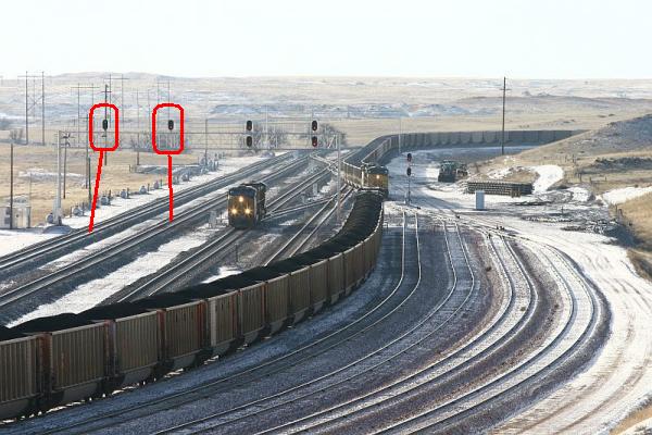
These govern the main tracks directly below.
In this case, one of the tracks is simply "straight through", while the other protects a track switch in the distance.
Given their location, these signal heads will show red, amber or green.
These signals are likely to be intermediate signals, telling the locomotive operator what will be happening further down the track.
"Red" means stop; there will be a rule book notation for the specific railroad if this particular indication at this spot means "Stop & Stay" or "Stop and Proceed at Restricted Speed".
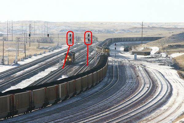
The next two signals on the bridge have two heads.
Had the two locomotives on the left been proceeding straight in the other direction, the signal indication would have been either yellow over red, or green over red; it depends upon the status of the next signal.
Had the locomotives been diverging from one track to the other track, the signal would have been either red over green or red over yellow, depending upon the indication of the next signal or depending upon the track layout.
What is not seen in this photo are the other signals for this interlocking plant, which are around the curve in the background.
The signals visible here are for trains going away from the camera, which these trains are not doing.
It is the indications of those unseen signals which determine the indications of these signals, giving the locomotive operators the instructions for their train speeds.
The locomotives moving toward the camera on the left probably were given green over red, while the coal train on the right may have been given red over yellow.
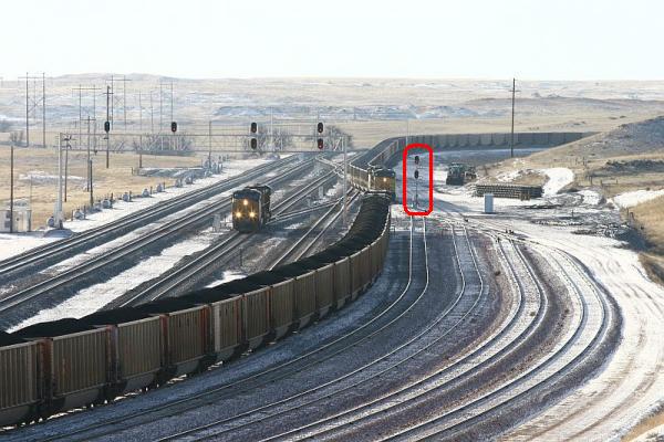
Looking at the tracks that converge on the right of the photo, you will see only one ground-level signal, which would seem to indicate that the five tracks on the right side of the four-track main line are unsignaled yard tracks.
This one ground-level signal governs the trains leaving those five yard tracks and entering the signaled environment of the main line railroad.
Since the coal train is entering a yard area, the signal it received around the curve in the distance may have been a combination of colors to tell the train operator that they would be entering an unsignaled area and that they would operate at "Yard Speed", which is to say, prepared to stop short of other yard movements, trains and obstructions.
Note that "Yard Speed" is not expressed in velocity but in terms of operating safety.
In this case, the signal indication depends upon the railroad and the era that you are modeling.
In earlier times, the indication may have been red over red over yellow, or red and lunar white, depending upon the railroad.
So, in your modeling practice, you also need to know the specific practices of your railroad, which means that having a company rulebook and timetable is very helpful.
Those reading this article are encouraged to leave a "Suggestion" with information which will further clarify this article.