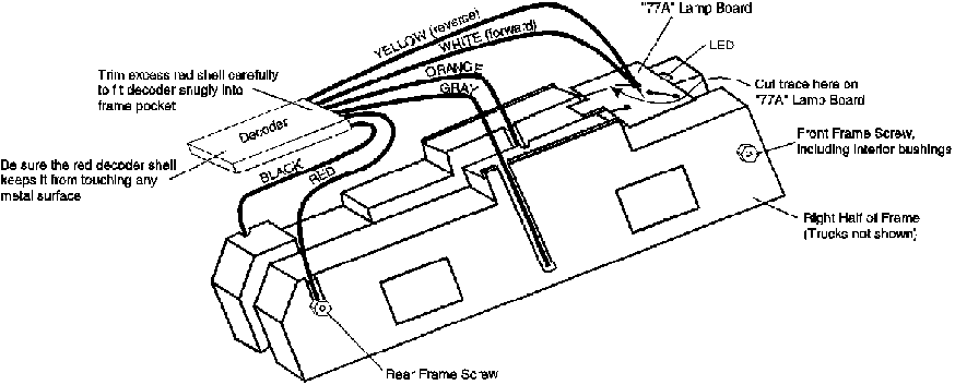
These instructions detail the installation of a wired Digitrax decoder (a DN140 in this example, but many wired decoders may be used) into an Atlas GP35 manufactured by Kato prior to September, 2007. These units are marked "Japan" on the bottom of the locomotive. Units marked "China" use a board replacement decodr such as the DN163A2.
Installation Diagram
Notes:
A. Be sure motor leads (Gray & Orange) do not touch frames & have protective insulation in place.
B. Be sure frame is straight & mechanism is correctly reassembled & can turn freely without binding.
Wired Decoder Installation Instructions
Follow these steps for decoder installation with either a replacement frame or an original frame that has been modified (See Modification Instructions below):
1. Disassemble locomotive, save original frame. Remove lamp bezel from upper rear of shell, keep all parts for re-assembly.
2. Locate Decoder on the back of the frame & note how long the leads need to be cut. Do not leave too much excess lead length. Snap in the motor and it's frame to check that the decoder wires will not bind the motor.
3. Remove the motor from the plastic motor mounting frame. Remove the brush caps & discard the flat brass contacts from underneath. Do not lose the brushes or small brush springs. Put a little solder on each brush cap top. Strip & tin the Gray & Orange Decoder wires.
4. Pass the Gray wire through the channel in the right side of the frame & solder it the outside of the brass brush cap. Reinstall it on the lower motor assembly with the brush & spring. Solder the Orange wire directly to the upper motor brush cap and reinstall on motor. Keep the solder mass as small as possible. Do not solder caps in place in the plastic motor frame.
Place 2 layers of thin insulating plastic or tape (e.g., Scotch tape) over brush caps & soldered motor leads. This insulation is very important to protect the decoder from motor brush to frame shorts that can cause damage. Note: Install + on the top brush and - on the lower brush for "head" first operation, if you reverse this, the engine will run tail first.
5. Re-assemble frame, motor drive, trucks, etc. Make sure that the motor and drive shafts spin freely before and after putting the two sides of the frame together. Place the Black decoder power lead under the rear left frame screw head. Use the plastic rear hex screw to jam the Red wire against the right frame, not touching the screw shaft.
6. Cut the trace as shown in the illustration above on the "77A" LED lamp board & solder the White lead to the LED terminal as shown in the illustration. For non directional lamp, also solder the Yellow wire to this same LED terminal. Push the 77A board into frame. If you wish to install the rear lamp, you will need a 1.5mm yellow LED and a 1Kohm 1/8th watt resistor. Solder the resistor to the anode side of the LED and the other end of the resistor to the left side of the frame (the frame nut works well for holding the end of the resistor). Then solder the yellow wire from the decoder to the cathode side of the LED and secure it so that it does not "flop around."
7. Test the loco on test track before replacing the shell.
Frame Modification Instructions
If you are not using a replacement frame, use the diagram as a guide and modify the existing frame as follows before proceeding with the instructions above:
1. Measure from the rear of the frame forward 1.04" for DN140 and similar decoders and mark the frame. Measure 7/32" (.218") down the side of the frame on both sides and mark the frame. This is the space you will need to remove to install the decoder. Be careful not to bend the frame while removing this material. Use a small milling machine, a file or a razor saw.
2. Drill a hole above the upper motor brush. With the frame halves together, measure approximately 1.5" forward from the rear of the frame. Before you drill, check that this spot is directly above the motor when it is installed. Drill a 5/32" hole on the spot marked in the center of the two frame halves. Next, cut a slot on the outside of the right frame half for the bottom brush wire. Use a motor tool with a ball shaped bit for this job.
3. Remove material from the inside of the motor cavity of the frame near the motor brush locations to allow clearance for the soldered wires on the brushes. Use a motor tool with a ball bit to do this. Locate the spot inside the frame where the motor brushes are located and remove some material, reinstall the motor & frame and check your progress. Repeat the procedure for the other frame half.
4. Using the motor tool and ball type bit, cut grooves for the pick up wires on both sides of the frame. Cut a small groove running to the Rear Frame Screw. This will allow you to attach the Black & Red Decoder Wires without having them rub against the shell when it is reinstalled.
5. When you have finished this modification, your frame should look similar to the illustration.