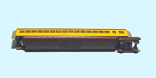
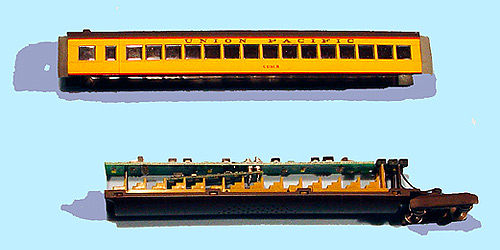
The image above shows the “M-10000 Coach Car B” for the N scale Con-Cor M-10000, which is the 1st car behind the loco. If you look closely, you can see the holes in the underbody, above which a speaker can be mounted for a sound decoder installation. The recommended Digitrax sound decoder would be the Digitrax SFX0416, but to use this decoder, one or more of the seat sections as shown below will need to be removed. There is a pocket that is designed for a speaker above the underbelly and under the center section of seats. The speaker that comes with the SFX0416 would need to be replaced with a speaker of the appropriate size.
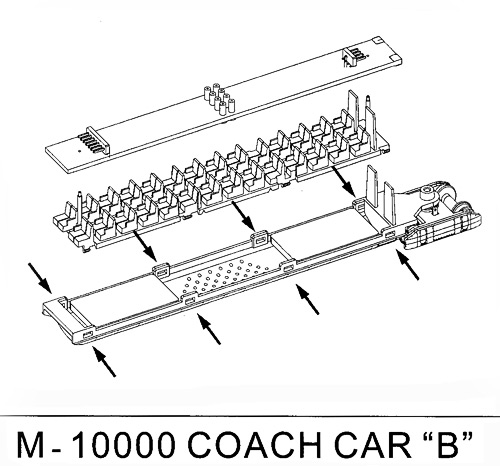
Step 1: Carefully remove the body from the frame per these Con-Cor’s Instructions: “Please note in the exploded view the gray arrows pointing to the “clips” on the chassis. It is important that you use a small wooden tooth pick or similar type prying device to remove the body shell. Simply place the wooden pick between the chassis and the plastic shell and gently pry the body shell up in all locations.” “CAREFUL: There is a chance that the chassis will fall from the body shell suddenly. Be sure you are supporting the chassis when removing the body shell.”
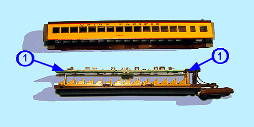
Step 2: As shown above, carefully remove the light board from its holders. The light board is held in place with two brass “pins” (See the arrows numbered 1 on this image). Then lay the light board upside down, locate the 8-pin dummy plug and gently pry it out of the socket with a flat head screwdriver. Once the dummy plug is removed, carefully insert the DN143IP, making sure to orient pin 1 to the pin 1 hole. The bulk of the decoder should be towards the front of the car as shown in the last image.
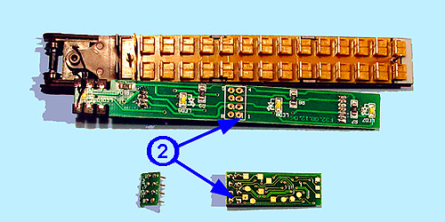
The above image shows the car with the body and the light board removed from the brass pins as well as the dummy 8-pin plug removed. It also shows the proper orientation for the DN143IP. The front to the car is to the right. You do not need to remove the two black truck pick-up wires on the rear corner of the light board. The wires have been engineered to have enough play to remove the board to remove the dummy plug and insert the DN143IP. Be sure to align pin 1 in the pin 1 hole! Pin 1 is marked on the light board and is the pin with the square base on the decoder. (See the arrows numbered 2 on this image).
This last image shows the DN143IP fully installed, with the light board snapped back onto the brass pins, ready for the body to be replaced.