KB78: Case Study: Nemo Junction - Basic Wiring Part 2 of 9
This article was last updated on June 3, 2011, 9:36 a.m. | Print Article | Leave Feedback
Although this is a simple railroad, it will have some advanced features. When the railroad's sectional modules are first assembled, the electrical connections are simple. The railroad will be controlled with a DCS50 Zephyr, using a PM42 Power Manager for short circuit protection. One section of the PM42 will control the inner oval of track, a second section of the PM42 will control the outer segment. This is done so that if a train derails on one loop, the train operation on the other loop will not be affected. Because the DCS50 is rated at 2.5 amps, the PM42 must be adjusted to work with the Zephyr (
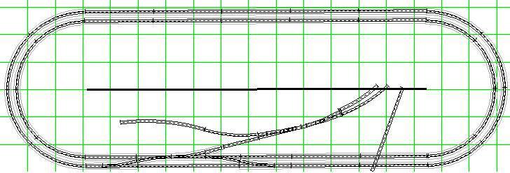
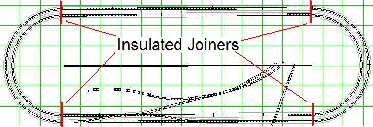
please see related article, below). Initially, the Nemo Junction modular railroad will simply be two ovals of operational track plus the junction. However, it is anticipated that the railroad will have signals, so the modules are divided up into 8 sections with insulated rail joiners, four pair on the inside oval and four pair on the outside.
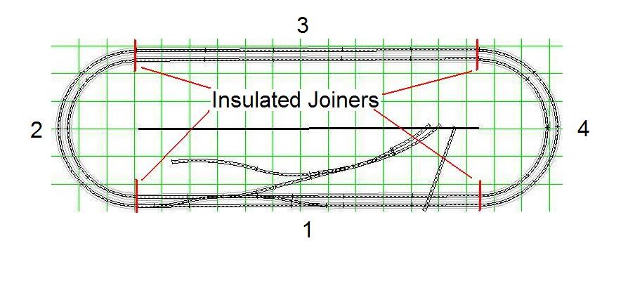
Feeder wires are then routed back to the Nemo Junction module. These feeder wires will be ganged together initially, and then later individually connected to two BD4's, which are used for train detection. To insure accurate connections, each segment of track is given an identification number; this is used only to identify the wires which connect to the Digitrax components. The outer loop is divided up into four sections, numbered 1 - 4.
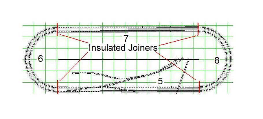
The inner loop is also divided up into four sections, numbered 5 - 8.
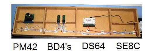
Here is the bottom layout of the various components:
Next:
Power Management