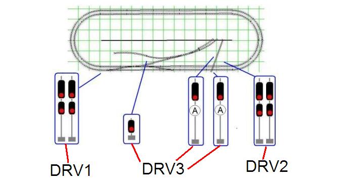
The Nemo Junction module has a total of seven color light signals that regulate the flow of train traffic through this interlocking plant.
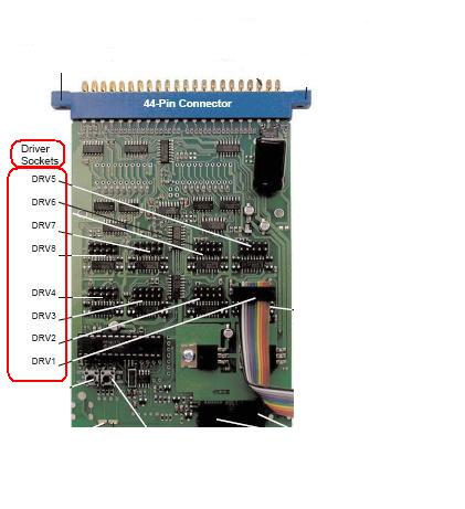
Controlling the Signals with SE8C The SE8C is the signal driver, sending current to the various LED's of the color light signals. Each signal is operated via switch commands from the Zephyr. The SE8C has eight Driver Sockets, identified as DRV1 - DRV8. :
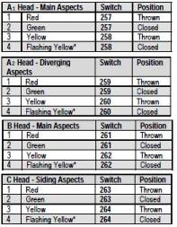
A Signal Driver Cable (a 10-conductor ribbon cable) is plugged into a SE8C Driver Socket to control as many as four signal heads per Driver Socket. Each signal head can display 4 lighting aspects, red (stop), green (clear), yellow (approach) and flashing yellow (advance approach). The signal is operated by sending a switch command from Zephyr to the individual signal head address. Using the default settings of the SE8C, Driver Socket DRV1 controls signal head A1 with SW257 and 258. That is, you put the Zephyr into Switch Mode, select switch address 257 and send a "Closed" command; the signal turns green. Sending a "Thrown" command to address 257 turns the signal to the red indication. In the same manner, sending a "Thrown" command to switch address 258 turns this signal to yellow. A "Closed" command makes the signal show a flashing yellow indication. Using the default settings of the SE8C, the entire SE8C is controlled by addresses 257 - 320. Driver Socket DRV1 controls a total of four signal heads, using switch addresses 257 - 264. The SE8C documentation includes this illustration:
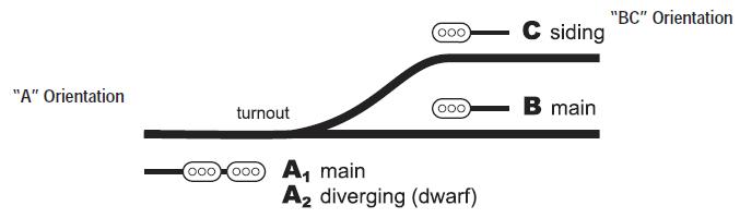
Note that the signal heads are identified as A1, A2, B and C. Although this illustration shows the four signal heads in one specific area, the SE8C could control four signal heads in different areas as long as they are connected to the same 10-conductor ribbon cable. Also, note the terms "A Orientation" and "BC Orientation"; how the individual signal is connected to the 10-conductor ribbon cable determines which switch addresses are used for an individual signal. For DRV1, here are the available switch addresses:
Once the installation is completed, a computer program will be used to coordinate the train occupation information with the signal indications and all that we are looking at here will be handled behind the scenes. The SE8C comes with a test signal which you can use to experiment with the different actions of the SE8C:
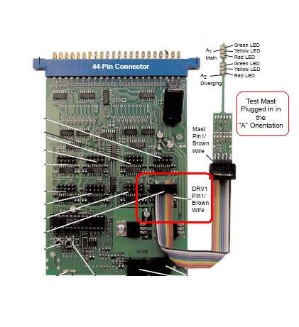
Here, a close-up of the test signal:

In this illustration, the signal heads are A1 and A2; if the signal were plugged into the cable in the opposite orientation, the signal heads would be B and C. The Signal Head Schematic The electrical schematic for each of the two head signals looks like this:
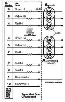
Although this may look intimidating, note the small comment at the bottom of the schematic:
Because the SE8C and the TSMK use 10-pin cable connections, wiring these signals is quite easy. TSMK The Terminal Strip Mounting Kit includes 2 terminal strip boards with resistors for easy installation. Each terminal strip board can handle from 1 to 4 signal heads.
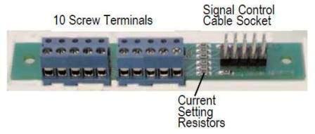
The 10-pin cable from a Driver Socket of the SE8C is connected at Signal Control Cable Socket of the TSMK. The individual signal heads are connected to the screw terminals at the other end of the TSMK.
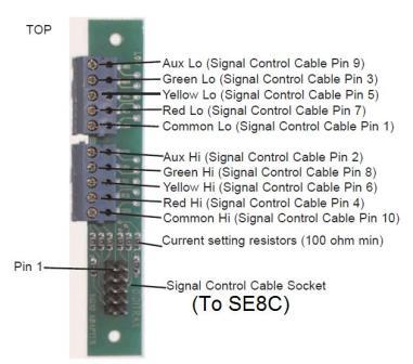
Note that the terminals of the TSMK correspond to the descriptions of the signal head schematic. Connecting the Signals Once the identification of the various signal heads has been completed, each is connected by way of a 10-conductor ribbon cable. Using the Signal Driver Cable Kit (SDCK), the ribbon cable is fitted at each end with a 10-pin plug; one end is plugged into the SE8C and the other is plugged into a Terminal Strip Mounting Kit (TSMK). The TSMK has screw terminals into which the individual wires for each signal are connected. The Color Light Signals
- There are two sets of paired signals for the two track main line, one set for eastbound trains and the other set for westbound trains.
- Two signals govern approaching trains on the imaginary railroad that crosses the double track main line.
- A dwarf signal which regulates trains approaching from the interchange and entering the two track main line railroad.
Of the seven color light signals used at Nemo Junction, only five will actually change indications; four on the double track mainline and the siding dwarf signal. The four active mainline signals have two heads:
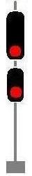
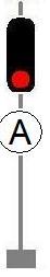
The westbound pair of signals will be connected to DRV1. The eastbound pair of signals will be connected to DRV2. The Dwarf Signal regulates train movements from the interchange track onto the main line:

The dwarf signal will be connected to the SE8C with Driver Socket DRV3. Since the North / South single track railroad is a dummy railroad, the two single-head signals will not change their indications.
However, the LED's of these signals still need to be illuminated, and we will use two of the remaining connections of DRV3 for that purpose.