Installation Notes:
1. Do not exceed the decoder’s 500mA total function output rating.
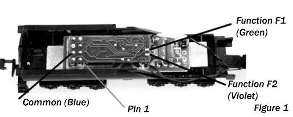
2. If you plan to use functions F1 (traditionally a green wire) or F2 (traditionally violet), the return, also called +Common or Lamp Common, should be made via a wire carefully soldered to the Common (or blue) pin indicated as shown in Figure1.
3. To use a function output with an inductive (coil) type load, you must install a kick-back suppression diode across the connections. If controlling a coil type load, such as an electromechanical relay or motor, shutting the device off can cause an inductive kick-back and eventually damage the decoder. Adding a diode to the wiring will allow this kick-back to be channeled back into the device instead of back to the decoder. The identification band side of the diode is connected to the common power (blue) wire.
4. See the Digitrax Decoder Manual for full details of wiring 12-16V lamps, 1.5V lamps, and LEDs. Lamps that draw more than 80 mA when running require a 22 ohm 1/4 watt resistor in series with the directional light function lead to protect the decoder.
5. Some locomotives employ filter capacitors for RFI suppression in the locomotive wiring. These may cause problems with Supersonic decoders and non-decoder analog operation on DCC. This capacitor should be removed for safe operation.