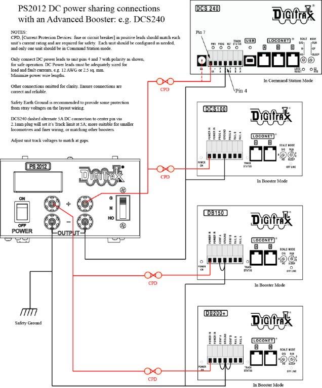
Connecting a PS2012 DC power supply to an “Advanced Booster” DCS240 and sharing with older Command Stations and Boosters:
The 2016 US DOE external power supply Efficiency requirements effectively require using DC input power and supplies for new-design products including our Advanced Command Stations/Boosters.
Digitrax does not recommend sharing a suitable DC supply for an Advanced type unit like a DCS240 with older Legacy Digitrax Command Stations/Boosters designed to run on AC output transformers. This is because the common Booster Ground (typically pin 4’s) and negative power return wires have a diode offset in non-Advanced (AC input) units that will cause an Advanced Booster to effectively carry all the return currents to any common power supply and possibly overload connectors in high load and/or fault conditions.
In the case of using the powerful Digitrax PS2012 12A/20A DC supply for a large layout, Figure 1 shows exactly how to avoid this problem, and share a PS2012 properly and safely with a number of similar and compatible Booster types.
The above figure notes a number of important points to ensure a safe and reliable installation. The PS2012 output current capacity exceeds most Boosters’, so each of the positive leads must employ a CPD, or Current Protection Device, such as; a fuse, polyfuse Y-cable or circuit breaker of a rating matching the unit, to protect the wiring and all devices from potential fault currents.
The wiring diagram ensures that all the Booster grounds shown on the track/power connector pin 4 only return with suitably sized wires back to the PS2012 negative terminals.
The PS2012 DC positive (after the CPD) is connected via pin 7 on all the connectors. To lower the DCS240 from 8A to 5A rating for; smaller layouts, shorter wiring and/or more delicate rolling stock, feed the e.g. DCS240 positive wire into the center of a 2.1mm barrel connector in the 5A jack as shown by the dashed line, instead of pin 7.
The required track wiring is not shown, but should also be sized as recommended for the Booster capacity (typically busses of 12AWG at 8A rating up to ~30’ runs, and multiple feeders at ~ 18 - 22AWG to each rail section) so when a rail section furthest from the Booster is shorted, the Booster reliably sees the short circuit.
The PS2102 can be set to 3 different output voltages, and the N-scale setting at 13.8V DC output provides the highest current capability of 20 amps. If you wish lowest unit heat-stress and maximum number of Boosters per PS2012, the N setting is the best to use. Since most HO locomotives are rated for 12V maximum sustained rail voltage, the PS2012 N-scale setting is also strongly recommended for HO layouts.
The number of Boosters connected should roughly match the PS2012 capacity. In most cases not all Boosters will be carrying maximum load capacity at the same time, so the PS2012 is unlikely to safety-shutdown for Overcurrent or Thermal Overload.