Power Management is a concern on every layout. With Digital Command Control, the main concern is that enough power is supplied to evey track section on the layout so that the digital signal is transmitted to the decoders in the locomotives and turnouts.
Each locomotive uses power from the track, some for the motor, some for headlights and other functions and some for the command control electronics in each locomotive. More electrical power is necessary to run more locomotives on the layout. Digitrax boosters provide between 2.5 amps & 8.0 amps. A small N Scale or HO Scale layout with two to four locomotives can operate successfully with a 2.5 amp booster. A larger layout running more locomotives will need more power. Additional power can be provided by using a booster with a higher amerpage rating or by adding multiple boosters to the layout.
As your railroad grows, increased power consumption needs are met by adding boosters, each with its own power supply. Each booster takes the DCC signal from LocoNet and the power to run the locomotives and transmits it to a power district, which is electrically isolated from other power districts on the layout. By electrical isolation is done by using insulated joiners or cuts in the rails at both ends of the power district.
You may decide to break down a power district into sub-districts to improve your operations.
Electrical short circuits are one reason for splitting a district into sub-districts. Whenever a locomotive or car derails and causes an electrical short, the circuit breakers in the control station and boosters shut the power to the layout off to avoid damage. Short circuits sometimes happen when a locomotive comes in contact with a turnout that is "set against it". When this happens, the power to the railroad shuts down, making it impossible to throw the turnout if it is controlled by the command control system.
Using a PM42, the track power and command control signal are divided up into four sub-districts, each isolated from the other, each connected to separate track power sub-districts or devices. For example, one PM42 could control two mainline track power sub-districts, a locomotive pit and the stationary decoders used for turnout control. If one of the track power sub-districts shuts down because of an electrical short, power is still available for trains in the other three sub-districts and for operating the turnouts. One or more of the four power feeds from the PM42 can also operate a reverse section.
The reverse section is an issue on two rail layouts because the electrical polarity cannot loop back on itself without causing a short circuit. This is illustrated here:
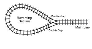
When the rails loop back on themselves, a short circuit is created on both rails. To prevent the short circuit cut gaps or use insulating joiners on both rails. On traditional layouts, electrical control of the reverse loop was done with toggle switches, one controlling the track electrical polarity on the main line and the other controlling the polarity inside the loop. In practice, this requirs vigilance by the train operators. Command control solves this problem by using electronics to sense the short circuit and automatically correct it so that the train keeps moving without operator intervention.
With the PM42, one or more of its sub-districts can be set up automatically operate a reverse loop; the PM42 can control up to four different reverse loops. The AR1 is a single unit automatic reverse section unit that is also avaialble.