The 5 Amp DCS100 and the 8 Amp DCS200 share the same front panel layout.
There is a variety of indicators, switches and connectors:
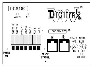
Power Input The two POWER IN terminals on all Digitrax boosters & command stations are the power input connections.
Power On Indicator This green LED indicates that the power to the DCS100 is on.
Ground Terminal The terminal marked ground provides electrical safety features and an RF ground reference for minimum radiated noise.
This should be the ONLY point of any DCS100 installation that is connected to the AC safety ground pin provided on most 3 pin 110V AC power sockets.
Grounding the system is a sensible safety precaution that should not be ignored.
RAIL A & RAIL B Terminals Use these terminals to connect the track to all Digitrax boosters and command stations.
If you are using more than one booster, always connect the same rail to the same terminal on each booster, for example connect all Rail A terminals to the right rail and all Rail B terminals to the left rail or vice versa on all track sections.
TRACK STATUS Indicator The TRACK STATUS indicator shows that there is voltage on RAIL A & RAIL B terminals.
The color indicates the type of signal.
If it is orange the track is getting DCC signals with no analog zero stretching.
If the color is green or red then a stretched zero signal is being used to operate a conventional locomotive.
When zero stretching is present, the DCC decoder equipped locomotives will read their digital commands normally and perform as commanded.
If the Track Status LED is not lit there is no voltage on the track, the track power to the DCS100 may be OFF.
OFF LINE Indicator The Off Line Indicator is for system temperature control.
PROG A & B The PROG A and PROG B terminals are the output for the second set of DCC signals which allow you to set up a programming track that can be used while the rest of the layout continues to run.
Prog A & B can also be used to set up braking sections on your layout.
This is useful if you want to stop trains at given points on the railroad, for example at a station.
LocoNet A & B These are the LocoNet connections which will form your railroad's data network.
Most Digitrax devices have LocoNet connectors, and commands issued by the Super Chief will be distributed to them via LocoNet.
You will use your LocoNet connections for the DT400 throttle which came with the Super Chief, other Digitrax throttles, and also the remote connection points around your railroad such as UR90, UR91 and UP5.
Please see the related articles. Scale & Mode Switches These are used to configure your DCS100 for your railroad.