This H0-scale railroad track plan first appeared in the Atlas Model Railroad Company's book "Six Railroads You Can Build", written by John Armstrong and illustrated by Tad Stepek. This book was first published in 1958 and has been reprinted several times. A classic bowl of spaghetti, the Transbay Interwoven has two reversing loops and a turntable.
DC Control
For DC operation, Atlas specified three Atlas Controllers (for the reverse loops and the turntable), two Atlas Selectors (to control eight track segments) and ten controllers for the railroad's turnouts.
DCC Makes Things Simple
With DCC, the wiring of this railroad is considerably simpler. Because each locomotive has a unique address, the section insulated gaps and the two Selectors are not necessary. Likewise, the three Controllers are replaced with autoreversing devices, although the double insulating gaps are retained (see below). The track switch controls can be replaced with command control devices, also.
How Much Power Will the Railroad Need?
Your first concern is to select a Digitrax Starter Set which is appropriate. Since this railroad will have only two trains running at any given time, and since there is storage space for an additional three locomotives in the turntable area, the calculations are fairly simple. A typical H0 locomotive will draw 600 MA when it is in operation. Locomotives sitting idle in the turntable area will also draw power, at the very least, 5 MA for the decoder. If each has LED lights, then it will typically draw 15 MA more; conventional light bulbs will draw 50 MA. If you have lighted passenger cars, these will draw current also; again 15 MA for LED's and 50 MA for light bulbs. For purposes of estimation, the Transbay Interwoven will have two trains in operation at any given time. One train will be a freight train with two locomotives and the other train will be a passenger train with one powered locomotive. The calculation:
- Three locomotives in operation, 600 MA@ = 1800 MA
- Three locomotives in the turntable area, 20 MA@ = 60 MA
- Four passenger cars with LED lights, 15 MA@ = 60 MA
Total power consumption = 1920 MA, or about 1.9 Amps
Which Starter Set?
The Zephyr Xtra is rated at 3.0 Amps, which should be sufficient to power this railroad. Likewise, the Zephyr Xtra has 20 "slots", (the limit of locomotive addresses that it can manage at one time). The planning assumptions are for a total of six locomotives, well within the range of the Zephyr Xtra. Because it is equipped with LocoNet, additions to the control system are easy, so signals and and other capabilities can be added as desired. If your railroad will be using more than the 3.0 Amps available from the Zephyr Xtra (such as locomotives with sound systems), you can add an additional booster, connecting it to the Zephyr Xtra via LocoNet, connecting to its own power supply and connecting this booster to its own section of railroad. Should you want more than one train operator, you can add Universal Panels like the UP5 that allow for multiple train operators or set up for tetherless operation, either with infrared or radio.
Turnout (Track Switch) Control
If you want to control the track switches with your command control system, then stationary decoders would be necessary. The DS64 controls up to four turnouts, so three DS64s are required for the Transbay Interwoven. Each DS64 would be assigned a unique Board ID, and then the individual turnouts would each be assigned unique addresses so that they can be controlled by the Zephyr Xtra or a computer program. Turnout control by remote buttons is also available with the DS64.
Power Management
Power management refers to devices which act as circuit breakers and power distributors. Power management tools help protect the railroad in the event of a short circuit. These devices also can be used for auto-reversing, a major issue for the Transbay Interwoven railroad, which has two reverse loops and a turntable.
Autoreversing
Return loops, or "reverse loops" are a traditional problem with two rail model railroads. When a track turns back upon itself, an electrical short circuit is created. That is, when a track turns back upon itself, the rails short out unless you place a pair of insulated joiners. There are several ways to approach this problem on a DC powered model railroad, all of which require changing the track polarity of one segment of the model railroad while a train is in another segment.
With DC, you create a defined segment of track which the train occupies while the track polarity is changed on the other segment of track. This segment must be longer than the longest train.
With a DCC model railroad, the solution to the problem is easy. Like the DC model railroad, you first create a defined segment of track which is longer than the longest train. Autoreversing works by detecting the short circuit and comparing the "phase" of the track power & DCC signal between two segments of track. With DCC, the track power is alternating current with the DCC waveform signal. While there is no "+" and "-" as with DC, there is still the need to make sure that when the locomotive passes into another segment of track, the phase of the track power and DCC signal are the same. Autoreversing electronically compares the two defined segments of track and switches the phase of the segment into which the train is moving to match that of the segment that the train is currently operating in.
The PM42 quad power manager can have each of its four sections set for autoreverse. The AR1 automatic reverser is a dedicated power reverser. Since the Transbay Interwoven has three situations where autoreversing is required, it is less expensive to use the PM42 instead of three AR1s.
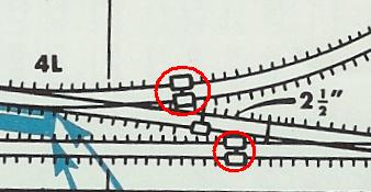
Defining the Reverse Loop Area With an example railroad plan such as the Transbay Interwoven, the hard work has been done for you already. That is, because the railroad is from a how-to-do-it book, the electrical issues have already been worked out; you simply cook-book your way through the project. In that way, the reverse loops have already been defined. A close examination of the track plan illustration will show you where to put the double insulating gaps, as shown. circled in red, below:
Because this track plan is complicated, it may help to identify the two different reverse loops. Reverse Loop 1
Reverse Loop 2
Each of these reverse loops are connected to one section of the PM42. The Turntable Because the turntable is wired so that power flows to the turntable rails, when the table turns from track to track, the electrical phase may, or may not, be correct, so autoreversing is used to coordinate power here, too. Each storage track is also connected to the main power bus of the railroad, while the turntable rail connections are connected to one section of the PM42.