The Crossing
The crossing allows tracks to cross each other at grade.
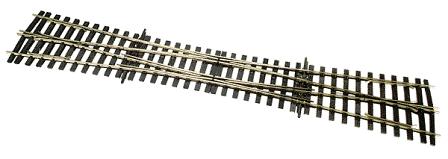
The Slip Switch
The more complex slip switch allows trains to both cross and to change tracks:
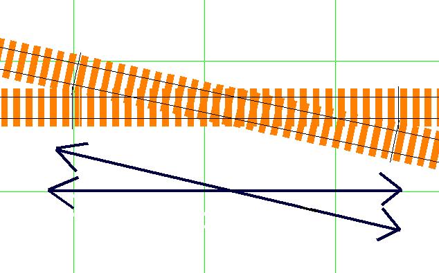
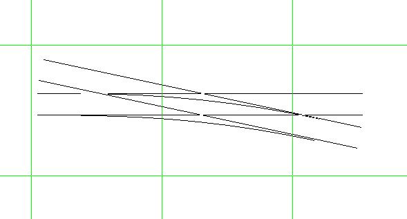
In the schematic below, you will note that the slip switch is more compact than ordinary turnouts. As a result, they are often found in high track density areas such as passenger terminals, where space is at a premium.
There are two varieties of slip switch, single slips and double slips.
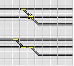
The Single Slip Switch
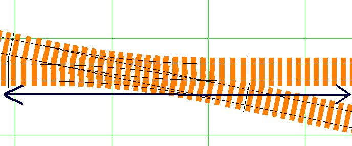
The single slip switch has a pair of movable points which allows trains to either cross or move from one track to another in one direction.
In operation, trains can cross another track:
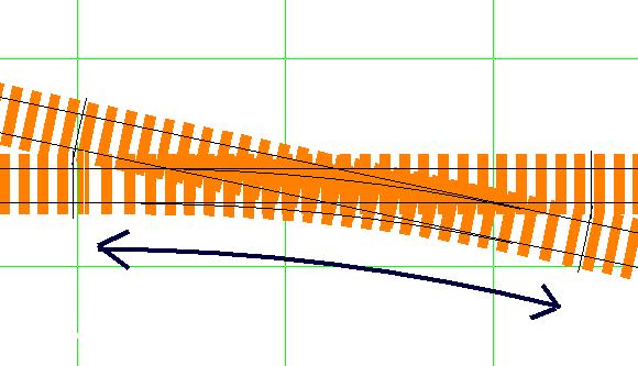
Or, trains can change tracks:
The Double Slip Switch
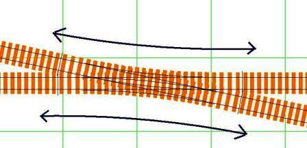
The double slip has an additional set of movable points which allows for trains to change tracks in two directions:
Model Railroad Slip Switches
Model railroad slip switches present two issues for the layout operator, providing power to the slip switch and control of the movable points.
Powering the Slip Switch
As with a conventional model railroad track switch (or turnout), you can use insulated frogs or electrified frogs. Many modelers choose to use electrified frogs because they offer smoother locomotive operation. The insulated frog turnout has a small segment at the frog which does not conduct electricity; while this simplifies matters, it also creates problems for some locomotives, especially those with a short wheel base and single truck units. What happens is that the locomotive passes over the insulated section and loses power. Longer locomotives do not usually experience this problem because they have more wheels that can pick up power from the segments of the turnout that carry power.
The electrified frog eliminates this problem but adds a couple more. You get a more reliable electrical path, but you must add additional insulated rails and wire them accordingly. In most cases, turnouts with electrified frogs use the movable stock rails to conduct power to the frog; when the turnout is set in one direction, then power flows to the frog from one rail. When the turnout is set to the opposite position, power flows from the other rail to the frog. If there are power feeders beyond the frog, then you will get a short circuit; this is solved by adding insulated joiners or gaps just beyond the frog.
Insulated Frogs
If the slip switch you have chosen for your railroad has insulated frogs, then powering the slip is a fairly straightforward matter. You simply need to maintain the correct rail power orientation, with the "black" rails being connected to the black power bus wire and the "red" rails being connected to the red power bus wire.
Electrified Frogs
Using electrified frogs on your railroad increases operational reliability, but it also adds an additional layer of complexity. This is especially true with slip switches; after careful study, you will note that the power to both individual frogs of the slip switch will vary with each point position. And, that the two frogs may have different power requirements in some situations.
Although there were hand thrown slip switches, it was much more common for the prototype railroads to use remotely operated turnouts. So it is with most model railroaders and you can provide the correct power to electrified frogs by using the additional contact points on advanced switch machines such as Tortoise, Tenshodo and others. However, you may find it easier to use the autoreversing features of power management devices such as AR1 or PM42.
Since the two frogs of a double slip switch may have different "polarities" at any given time, this means that you must use two AR1's or two sections of the PM42. Because the autoreversing feature is automatic, by sensing the power phase and adjusting it to meet required conditions, you are spared some of the complexity that accompanies wiring slip switches.
Automatic Routing
As you have noted, the slip switch can be a complicated device. Some slip switches, particularly those from European track manufacturers, have an internal set of linkages so that one switch machine controls all the moving points of the slip switch. In other cases, two switch machines are required to properly operate the slip switch, and there is at least one example of a slip switch that required four switch machines to operate.
This can be simplified by using the automatic route capabilities of both the Super Chief or the DS64. Please see related articles (below).
The Prototype
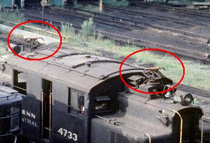
Like model railroads, some of the real railroads experienced power problems with slip switches. In particular, the New York Central (in the New York City segment of the railroad) and the Cleveland Union Terminal operations needed a special approach to slip switches. Both roads used outside third rails to provide electrical power to their locomotives. Since these operations were in densely populated areas, they frequently used the slip switch to save space.
At the same time, the outside third rail could not be placed in the crossing area of the slip switches, nor were the locomotives long enough to bridge the gap, leaving trains briefly without power in that critical area. Rather than relying upon momentum to get the locomotives through this unpowered area, the railroads installed a small segment of powered overhead wire and equipped their locomotives with small pantographs (described by Paul Mallery as a "pantograph shoe").