
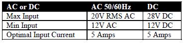
The two “POWER IN” terminals on all Digitrax boosters & command stations are the power input connections. Please see the related articles about power requirements for the DB150.
Power Supply
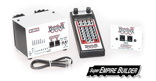
Digitrax recommends the PS515 power supply to power the DB150.
There are many other transformers and power packs that can supply the input power for the DB150.
Check with your Digitrax dealer for suggestions.
Most regular DC model railroad power packs are not able to supply 5 amps to the DB150 booster, because they were designed to run only 1 or 2 locomotives in a DC blocked system.
With DCC you’ll be running multiple locomotives in the same power district so, you’ll need to provide more power to each district.
When power to the unit is switched off, wait 30 seconds before turning on the power again.
It is normal for the DB150 to be warm to the touch when it is in use.
It is designed to absorb and dissipate the power difference between the input voltage and the selected scale output stabilized voltage, at the current load being drawn.
If the unit is not able to dissipate excess heat, over temperature thermal shutdown may occur.
We recommend that you locate the boosters in a location where they can dissipate heat.
If you experience frequent over temperature shutdowns, add a small fan to help cool the booster.
Power On Indicator
This green LED indicates that the power to the DB150 is on.
Ground Terminal
The terminal marked ground provides electrical safety features and an RF ground reference for minimum radiated noise.
This should be the ONLY point of any DB150 installation that is connected to the AC safety ground pin provided on most 3 pin 110V AC power sockets.
Grounding the system is a sensible safety precaution that should not be ignored.
RAIL A & RAIL B Terminals
Connect these terminals to the track on all Digitrax boosters and command stations.
If you are using more than one booster, always connect the same rail to the same terminal on each booster, for example connect all Rail A terminals to the right rail and all Rail B terminals to the left rail or vice versa on all track sections.
TRACK STATUS Indicator
The “TRACK STATUS” “ indicator shows that there is voltage on the track.
The color indicates the type of signal.
If it is orange the track is getting DCC signals with no analog zero stretching.
If the color is green or red then a “stretched zero” signal is being used to operate a conventional locomotive.
When zero stretching is present, the DCC decoder equipped locomotives will read their digital commands normally and perform as commanded.
If the Track Status Indicator is not lit there is no voltage on the track, the track power to the DB150 may be OFF.
OFF LINE Indicator
The DB150 automatically shuts down when the heat sink temperature rises to around 45 to 50 degrees Celsius and the “OFF LINE” indicator will glow red.
The DB150 automatically resumes operation when the heat sink cools down to approximately 40 degrees Celsius.
The “OFF LINE” indicator will also be lit when there is no track status.
This is normal and you should not be alarmed.
CONFIG A & B
The “CONFIG A” and “CONFIG B” terminals allow the DB150 to be set up as a command station, a booster or an auto reversing booster.
LocoNet Connection Jacks A & B
These LocoNet Connection Jacks let you expand your Digitrax system by simply plugging LocoNet devices in to the system.
Either jack, or both jacks, can be used in any given configuration.
MODE Switch The 3 MODE switch settings are:
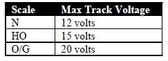
The N scale setting is sufficient for most HO operations and provides an extra safety margin.
The track voltage can be adjusted if necessary.
Please see the related article.
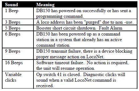
DB150 Audible Sounds
The DB150 uses several diagnostic beeps and clicks detailed below: