Brandywine & Benedictine
The Brandywine and Benedictine Railroad (B&B) is an Appalachian coal hauling railroad set in the mid 1950s. The layout is HO scale, it was owned and built by Norm Stenzel. This case study was originally presented as part of the “Digitrax Big Book of DCC” and it has been reproduced here from that text. This study was originally presented as part of three chapters about DCC Installation based on different layouts. The other layouts discussed were the Sante Fe & Western and the Norcross Southern. It is recommended that you read these studies as well as some of the topics overlap.
Brandywine & Benedictine
The Brandywine and Benedictine Railroad (B&B) is an Appalachian coal hauling railroad set in the mid 1950s. The layout is HO scale. The B&B was featured in Model Railroader Magazine in May 1995, on the cover of Model Railroading Magazine in February 1998 and in Allen Keller’s Great Model Railroads™ Volume 20 video tape. Figure 5-1 is the track plan for the B&B. Norm Stenzel, the owner and builder of the layout, moved to a new house at the end of 1998. The new house came with an unfinished basement about three times larger than the old one. Planning for the new layout is nearly complete and construction on the “B&B 2000” was beginning when this article was written.
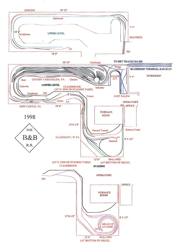
Figure 5-1: Old Brandywine and Benedictine track plan
Norm, who runs the layout using prototype operating methods with a regular operating crew, has decided to rebuild the layout to improve operations as much as possible. His previous layout space was cramped. His design objectives for the new layout are:
a) Keep the basic flavor and operating scheme of the previous layout.
b) Add more staging yard space.
c) Increase most aisles to four feet in width, with a minimum of three feet everywhere.
d) Make the trains and their supporting trackage 25% longer.
e) Add more staging yard space.
f) Increase the number of passing sidings from four to at least six.
g) Develop the Bottom Creek Subdivision into a fully functional branch line.
h) Add more staging yard space. (No, this is not a typo, more staging yard space is really important!)
Layout Analysis
The finished track plan for the new B&B is shown in Figure 5-2. Because of the windows located along two sides of the basement, much of the exterior wall space will not be used for the railroad. Since Norm has just started construction of the new layout, the word “finished” can be taken with a sack of salt. Any additional changes to the track plan are expected to be small details rather than large conceptual changes.
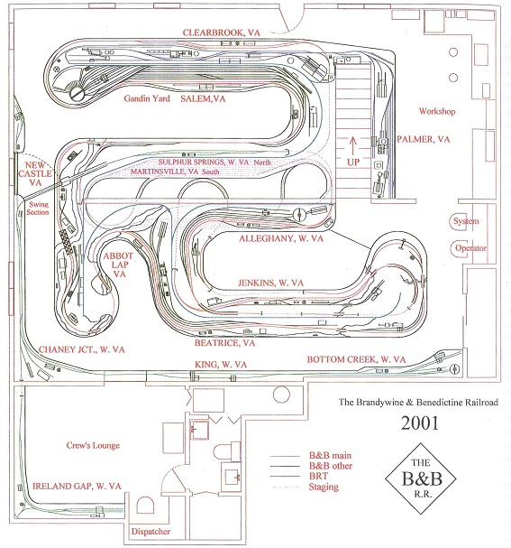
Figure 5-2: New Brandywine and Benedictine track plan
The operating scheme of the new layout is practically unchanged from the old railroad. There are more than twice as many staging tracks in the new plan and each of these staging tracks is nearly twice as long. The regular aisle width is four feet, except for the two foot wide aisle between the backdrops for access to the staging yards. The train length will not be increased, instead there is more single track mainline between locations and there are now seven passing sidings. The Bottom Creek Subdivision is a complete self-contained branch line over 100 feet long; think of a large version of Tony Koester’s Coal Fork Extension. The mainline is about 60% longer, exclusive of the staging yards, which will increase headways between trains, running time and reduce congestion in the yard.
The old B&B was built to use conventional control and was later converted to DCC . The B&B is a steam/diesel transition era line and most steam trains are powered by a single road locomotive, most of which are brass imports with can motors and very free running drive trains. During a normal operating session, the railroad could have been run as a single power district from a single 5 amp booster, but it wasn’t. For reasons of operating reliability, the mainline was divided into three power districts. Salem yard was divided into two power districts, one for the yard and one for the engine terminal. The new layout will be organized in a similar manner. Instead of additional power districts however, Norm will divide up his power districts into several power sub-districts. A dedicated fast acting isolation device, like one element of a PM4 power manager, will protect each power sub-district.
The new B&B is too complex to consider using whole layout common return wiring, so direct home wiring is used. The track will be divided into four power districts: Mainline, Salem Yard, Bottom Creek Subdivision and Staging. These districts are shown in Figure 5-3. If this were an existing layout being converted to DCC, it would be converted from whole layout common rail wiring to direct home wiring by cutting a gap in the common rail everywhere power districts adjoin. A total of five new gaps would need to be cut. At the same time, the common return wiring would be divided to provide isolated feeds for each of the four track districts.
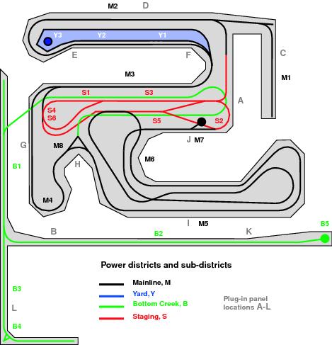
Figure 5-3: Power districts, sub-districts, booster, and plug-in locations
Each of the power districts will be further subdivided into twenty-two power sub-districts that are shown in Figure 5-3.
S 1,2,3,4,5 and 6
Y 1,2 and 3
M 1,2,3,4,5,6, 7 and 8
B 1,2,3, 4 and 5
These sub-districts were created to increase operating reliability. With these sub-districts, no district should be able to overload any booster with operating current demands beyond the booster’s capability. If an operator tries to go through a turnout the wrong way, or derails a train, only the sub-district affected will shut down. Some of these sub-districts are reversing sections. There will also be a separate power district for turnout control and another one for the detectors and signal system. While Norm will use some slow motion turnout motors on the mainline, the majority of the turnouts will be hand thrown. If the operating current of all of the turnout motors or the power drop in the district power bus is too great, then a second power district will be created for the turnout motors to divide the load evenly between two boosters. Other railroad animation, like working railroad crossing gates with bells and lights, will be installed on the layout. On the B&B, the power load will be spread across more than one household power circuit, so a short, for example, in a power tool or a light fixture won’t affect the whole layout.
The power bus for the Bottom Creek Subdivision will exceed fifty feet in length, but the power bus for the other track power districts will be less than fifty feet. To minimize the length of the wiring and power bus wires, the power supply and booster for the Bottom Creek Subdivision will be located near B in Figure 5-3, near the crew lounge. All the other power supplies, boosters and the command station will be located near A at the end of the staging yard aisle.
With a layout of this size, wireless control is the best choice and Norm’s previous experience has borne this out. Some of the local switching will be run with tethered throttles, especially where a location has its own switcher. It will be simpler to use radio throttles rather than infrared for a layout like this one that is divided by walls. It would take at least seven infrared receivers to give enough coverage because of the way the room is set up. Upon checking the room for problems with radio reception, there is nothing that looks like it will present problems for radio operation of many throttles with a single radio receiver. The radio receiver will be installed near A where there is an outlet for its auxiliary power supply.
Why would we even consider infrared? Because at the time of publication, radio control was only available in the US, Canada and New Zealand. So, in some places, infrared wireless control may be your only wireless choice.
Plug-in panels, which are needed for tethered throttles, for acquiring locos on wireless throttles or in an emergency will be installed at the lettered locations on Figure 5-3, for a total of one radio receiver panel and eleven regular plug-in panels. Other plug-in panels can be added later if needed, this is a simple matter of installing the panel in the fascia and plugging it in to LocoNet. The layout will have a dispatcher’s desk in the workshop. Although it will not be implemented in the beginning, provisions will be made for computer control and computer assisted dispatching.
When the power sub-district boundaries were identified, eight reversing features were also noted:
- three reversing loops, S2, S4, S6
- two wyes, B4, M8
- three turntables, B5, M7, Y3
Because this is an essentially linear track plan with simple routing options, it is easy to identify the correct location for the double gaps at the end of the reversing sections. In layouts with many complex routes and/or “spaghetti” mainlines, the identification of reversing sections may be much more complex. The easiest way to work on this problem is to draw a track plan and schematic with all the spurs and secondary trackage eliminated and then follow an imaginary train around the trackage to locate the reversing sections as we did in the Norcross Southern example.
If the new B&B layout were wired for conventional control, it would need at least four mainline cabs, five local cabs, extra cabs for the staging yard, Salem Yard and the Bottom Creek Subdivision with all the associated control wiring. With DCC only one LocoNet cable is needed to accomplish the same thing.
Detectors
To provide input for the signaling system, for computer assisted control and to activate the operating railroad crossing gates, both the Norcross Southern and the new Brandywine and Benedictine will use track detectors. The mainlines and passing sidings will be divided into a series of detection sections by cutting gaps in one of the mainline rails and a detector will be inserted into the track feed for that rail. This is shown in Figure 5-4.
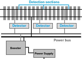
Figure 5-4: Detection section wiring
There are two different kinds of detectors: occupancy detectors and transponder detectors. The occupancy detectors used are simple high sensitivity detectors designed especially for DCC use. To register on or occupied, the resistance between the two rails must be less than about 10k Ohm. When the detection section is unoccupied the resistance between the two rails will be near infinite. If the two rails are connected by a small piece of metal, the resistance will be near zero. A locomotive, even stationary, will have a resistance less than 10k Ohm, so will railroad cars with resistor wheel sets or with wheels connected by conductive paint. You cannot connect any other device across the rails in a detection section because it could lower the resistance enough to trigger the occupancy detector. The output lead of the occupancy detector can be used as the input for another control device.
The Digitrax transponder detector is a specialized logic device. It can function as an occupancy detector, but its main purpose is to operate in conjunction with transponders. A transponder is a small electronic device which can be installed in any piece of rolling stock and programmed with an address. In the case of a locomotive, the transponder may be part of the DCC decoder installed in the loco or it may be a completely separate device. If it is part of the decoder, then the decoder address will be the transponder address. Transponders broadcasts acknowledgement messages that include their address to LocoNet. Transponders may also send additional information to the detector such as speed, direction and consist information. A transponder detector can tell that its detection section is occupied and also with what. This is shown in Figure 5-5. The transponder detector is also capable of recognizing multiple transponders within its detection section. The BDL16 occupancy detector can have four or eight transponder detectors added to it. The information from the transponder detectors is reported over the LocoNet to the command station, signal controllers, some stationary decoders and other LocoNet devices. When deciding where to put the detection sections, make allowances both for the needs of the signaling system as well as for occupancy detection. For the B&B it will be easier to cut the gaps and install the track feeds for the detection sections during the construction process, but if changes are needed, adding more detection sections and track feeds is really not that difficult.
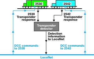
Figure 5-5: Transponder detection
Stationary Decoders
Stationary decoders are commonly used for turnout contol. Now let’s take a look at how they are used for other purposes on the new B&B.
One common use for stationary decoders combined with occupancy detectors is to operate crossing gates automatically when a train approaches the grade crossing. Figure 5-6 shows how to wire an occupancy detector and a stationary decoder to the track, along with flashing LEDs, a sound module and a crossing gate solenoid.
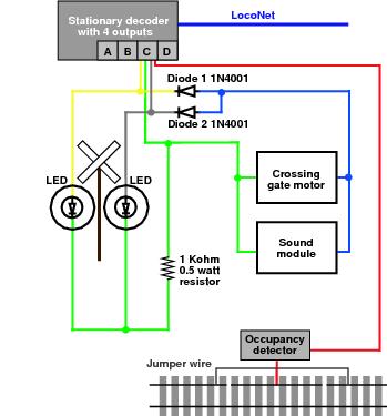
Figure 5-6: Automated crossing gates
Let’s look at the various wiring components. The flashing lights are two LEDs protected by a 1k Ohm ½ watt resistor. One light is controlled by the “thrown” stationary decoder output and the other light is controlled by the “closed” output. Both lights are connected to the common raw 12 volt power output of the decoder. Digitrax stationary decoders can have their outputs programmed to control lights with various flashing rates. The two LEDs are wired so that each light is connected to a lead that is set to pulse every second and the LEDs will flash alternately. To keep the circuit simple, two 1N4001 diodes, D1 and D2, are used to provide power to the crossing gate solenoid and the sound module whenever the lights are flashing. The stationary decoder is programmed to operate the lights when the occupancy detector is tripped. The detector will set the input lead to the decoder to “on”, just like a switch, and when this condition is detected by the stationary decoder, the output to the lights, solenoid and sound will operate. More than one occupancy detector could be connected to a single stationary decoder. For the simplest track installation, the detection section of track should extend on either side of the crossing to the point at which you want the crossing gates to activate. A manual switch on the fascia can be added to turn the detector or decoder off if a loco is parked for an extended period in the detection section, but not blocking the crossing, so that the crossing gates and flashing lights do not continue to operate. For the crossing gate to work as intended, the last car in the train must continue to activate the occupancy detector, even though the locomotive may have left the detection track section so, the last car will need a resistor wheel set of 10k Ohm or less.
If you are using this kind of automated crossing gate, it is a good idea to have all your cabooses and cars fitted with FREDs be permanently equipped with resistor wheels to trip the occupancy detectors. An example of how to arrange the detection section with gaps is shown in Figure 5-7. Other situations might require more complex wiring with one detection section turning the lights on and another turning them off. The jumper wires around the detection section shown in Figure 5-6 are required only if either of the two rail sections on either side of the detection section does not have its own power feed. As mentioned earlier, to simplify debugging wiring problems, cut the gaps for the detection section in the rail connected to the B side of the booster only.
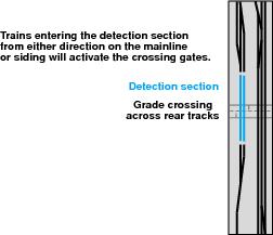
Figure 5-7: Example grade crossing location
Another simple use for an occupancy detector and a stationary decoder is in a helix. On a layout where a helix is used, the train is usually out of sight for an extended period. If an occupancy detector is connected to a detection section on each lap of the helix, a light can be wired to a panel in the fascia to show progress along the track. Add a stationary decoder and a sound unit could also be used to generate whistle sounds for hypothetical grade crossings on the hidden part of the route. In any case, the train engineer can tell that the train is still running and can tell approximately how long before it appears on the visible track simply by counting whistle noises or the number of times lights go on and off.
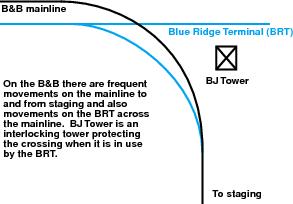
Figure 5-8: Blue Ridge Terminal interlocking
There is an interlocking tower where the mainline of the Brandywine and Benedictine crosses the track of the Blue Ridge Terminal (BRT) near the exit from the staging yards. The trackwork in this area is shown in Figure 5-8. There will be frequent movements on the B&B mainline to and from the staging yard and much less frequent movement on the Blue Ridge Terminal across the mainline. Since some of the mainline trains may be run by operators in the staging area, or near Salem, who might not be able to see the crossing, it would be useful to be able to protect the crossing when it is in use by the Blue Ridge Terminal. The simplest method is shown in Figure 5-9. The Blue Ridge Terminal engineer activates a switch that cuts the power to the B&B mainline when the BRT is using the crossing. This is simple and effective, unless the BRT engineer forgets to re-activate the mainline when he is done. Figure 5-10 shows a more elegant method. As long as the detection section on the BRT is occupied, the occupancy detector signals the stationary decoder, which in turn operates a switch, to turn the power off for the B&B mainline, allowing sufficient distance for the train to stop on either side of the crossing. The BRT engineer can see if any trains are coming before he enters the crossing, so the only problem left is traffic on the B&B mainline. One option here is to have the B&B run by computer control from the staging yard to Salem and the BRT run by a human operator.
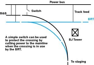
Figure 5-9: Simple control switch
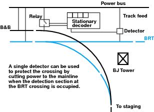
Figure 5-10: Single detector interlock
A more sophisticated interlocking could be achieved by using two switches, as shown in Figure 5-11. The normal state is power to all tracks. The first train to arrive will trip the detector and its associated stationary decoder. It will then turn the power off to the other track and detection section. Power is restored to the other track when the train leaves the detection section. If, in the meantime, this interlocking has stopped a train, as soon as the detection section and track powers back up, the presence of that train will turn off the power to the other route and the train will restart. Because this system is simple, there is no check for the ends of the train entering and leaving the interlocking plant. Because of this, the detection section must remain on for as long as the crossing is blocked. The detection section needs to be at least as long as a train. This will prevent a situation where the crossing is blocked but the loco has left the detection section and the caboose hasn’t entered the section yet. Remember that all the cabooses on the B&B and BRT will activate detection sections.
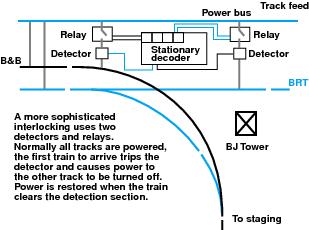
Figure 5-11: Two Detector interlock
A more complex system could be wired using multiple detectors and stationary decoders which explicitly turn the power on and off. Working signals could also be added to show the current status of the interlocking. Instead of merely turning the power off, the decoder could control working derails ; this is more prototypical for interlocking, but deliberately derailing the trains is more brutal.
Programming track
DCC decoder equipped locomotives and rolling stock equipped with transponders need to have their various features and functions set up or programmed. DCC programming is much like programming a VCR, not like programming a computer. The programming commands are sent to the decoder installed in the locomotive to be programmed through the rails just like any other commands. Some programming commands are acted on by all the locomotives that receive them and others are addressed to specific locomotives. Most of the time you will want to change the programming of one specific loco. The last thing you want is to unintentionally program other locos at the same time. Care must be taken to be sure that certain programming commands, like a new address, are not sent to every loco on the layout by mistake. It is not a pretty sight when you have programmed every loco on your layout to address “10” and they all move together when you try to run the one you thought you just programmed. The simplest solution to this problem is to provide a separate programming track where you can program one locomotive at a time.
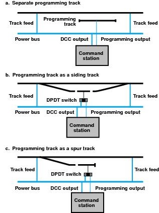
Figure 5-14: Connecting the programming track
The command station generates the programming commands. Most DCC command stations generate broadcast programming commands that are sent to everything on the attached rails. This means that to program decoders, you will need to shut down layout operations temporarily while you are programming. The Digitrax DB150 when used as a command station works this way. Other command stations, like the Digitrax DCS100, have a separate set of programming outputs that can be used while the layout is still operating to do programming. In either case, the simplest solution is to provide a completely isolated section of track, not connected to anything else, where you can program your locos. This arrangement is shown in Figure 5-14a. If you want to avoid handling your locos with all that putting on and taking off the programming track, then use the arrangement shown in Figure 5-14b or Figure 5-14c. The programming track is a section of track, double gapped and controlled by a double pole double throw switch. In one position the DPDT switch provides power to the programming track from the power bus. In the other position, the DPDT switch provides programming commands to the programming track from the special output on the command station. To use the programming track, run the loco onto the track, switch to programming, program the loco, switch back to normal and run the loco back to the rest of the layout. To insure reliable programming, keep the programming track near the command station so that the wires from the programming outputs are as short as possible.
As mentioned earlier, not all command stations have separate programming outputs. For command stations that do not have separate programming outputs, the command station itself is put into program mode and broadcasts its programming instructions to all locos on the track. The DB150 command station works this way. On a conventional block wired layout, you can take advantage of the existing block wiring to set up a programming track. To program a locomotive, simply turn off all the other blocks on the layout, leaving on only the block which contains the loco or locos to be programmed. In practice that would usually be a block associated with the engine facility or the yard. If block selectors were not available, then you might use the arrangement in Figure 5-15. In this example, a simple switch turns off the power bus from the entire layout except the programming track. The loco can be run onto the programming track, the power shut off to the rest of the layout, the command station set up for programming and the loco programmed. Reverse these steps to return to normal operation. Again, keep the programming track close to the command station so that first set of track feeds along the power bus are used to drive the programming track.
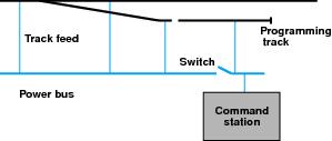
Figure 5-15: Programming track power bus switch
The new Brandywine and Benedictine will have several programming tracks. At A on Figure 5-3, near the staging yards, there will be a programming track fed from the command station’s programming outputs. A separate feed from these outputs will be run to selected tracks at the Salem roundhouse and diesel facility. Manual switches will control track power and programming on these selected tracks.
Turntables
When a turntable is installed on a DCC layout, there are two main issues to consider: polarity control and rotation control. A turntable is a reversing section, as illustrated in Figure 5-16. The loco enters and leaves on the same rails, without reversing the loco’s direction of travel.
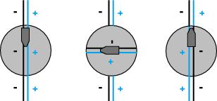
Figure 5-16: Turntable track polarity
To control the polarity on a conventional layout, the power supply to the turntable bridge can be supplied in a number of ways. The polarity of the bridge rails must match that of the lead rails and the engine stall rails. The best way of doing this is for the power to be carried by some sort of split ring or pit rail wiper pickup so that the polarity of the bridge rails changes as the turntable rotates. Effectively the turntable bridge is a rotating switch. The loco moves forward onto the bridge, the turntable rotates, the direction of the loco is reversed and the loco moves forward off the bridge. Provided that the wipers don’t short across the gaps when the turntable rotates, this method can also be used with DCC. Less sophisticated turntables, use a DPDT switch to control the polarity just like a reversing section. This method can also be used with DCC. An automatic reversing booster or most of the other automatic reversing devices that are available are other options. Simply connect an auto reversing booster or device to the bridge rail power supply and when the loco moves off the turntable the polarity of the bridge is automatically matched to that of the lead and engine stall tracks. Unlike conventional control, since the front of the locomotive is always the forward direction with DCC, you may need to reverse the loco’s direction with the throttle to get it to move off the turntable in the direction you want.
The simplest form of motion control for a turntable is to use a mobile decoder to control the turntable motor. Using this method you can have fine control of the turntable speed and you can drive the turntable from any throttle. Using a throttle it is possible to run the loco onto the turntable bridge, operate the turntable and then use the throttle to run the loco off the turntable again. Simple indexing can be achieved by wiring lights to the contacts in the end of the turntable bridge. When the bridge is properly aligned the appropriate light comes on as shown in Figure 5-17a. If the bridge motor runs freely, at slow speed it can be made to stall easily, so a simple notch and tang can stop the bridge when is properly aligned. To move the turntable, keep enough power going to the motor to overcome the resistance of the notch. At slow speed when the turntable stops, just turn the throttle down to stop the motor. This arrangement is shown in Figure 5-17b. More sophisticated arrangements for indexing a turntable can be set up using a stationary decoder and switches connected to the two input leads. The decoder can be programmed to stop whenever a switch goes from off to on. If the switch is mounted on the bridge, then a simple cam can be used to activate it. An occupancy detector operating between the end of the bridge and the pit wall or the pit rail could also signal the turntable motor to stop. You have many choices for turntable operation and control.
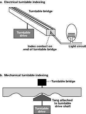
Figure 5-17: Simple turntable indexing methods
Train Order Signals
Train order signals, working or otherwise, are not often modeled. These signals are usually found in pairs, one signal for each direction of travel, at nearly every occupied depot. They can be used for manual block system train control. Train order signals are either semaphore or color light and usually have two or three indications: OK no orders, slow to pick up orders (optional) and stop to pick up orders. The Brandywine and Benedictine operates with train orders in an era where there were no radios on the trains. Train order signals are used at each open depot to indicate to the train crew whether or not orders must be picked up. The signals on the B&B have only two indications, clear and stop for orders. The B&B has a dispatcher’s panel that generates train orders and communicates by telephone to the operators at the depots and sets the train order signals. Each train order signal is controlled by its own accessory decoder driven by the power district for the B&B signal system. This is illustrated in Figure 5-18.
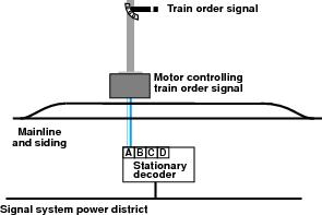
Figure 5-18: controlling train order signals
The train order signals can be of the three types shown in Figure 5-19 a, b, and c. The semaphore signal is operated exactly like a turnout and can be driven by any of the three motor types suitable for turnout control. Thrown means “Stop For Orders” and closed means “No Orders.” (Train order stations that are open only part of the day set their train order signal to “No Orders” when they are closed.) The single lamp signal uses a bi-color LED that shines red or green depending on the direction of current flow through it. It is driven by the same sort of circuit as is used by the slow motion turnout motor. When LEDs are driven like this, a resistor must be used to bring the power down to a level that the LED can handle. The LED is installed so that it shows green for closed and red for thrown. The train order signal with separate lamps is driven like the two LEDs in the crossing gate example. The stationary decoder is configured for steady output. The green LED is connected to the closed lead and the common lead. The red LED is connected to the thrown lead and the common lead. When the dispatcher has train orders, the appropriate train order signal is set to thrown. The train crew stops, picks up the orders or calls the dispatcher on the telephone at the depot. The signal can be cleared by the dispatcher or one of the decoder input leads can be connected to a fascia mounted switch so that the train crew can clear the signal. When the crew uses the switch to clear the signal, an indication is sent back to the dispatcher that the train crew has acknowledged receipt of the train orders.
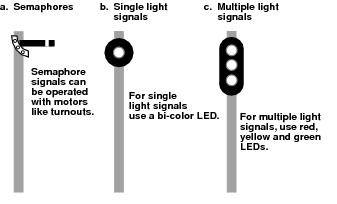
Figure 5-19: Types of train order signals
Signals
The Brandywine and Benedictine will both have signals. The signal system may not be installed in the beginning, but provisions will be made for signals during the construction of the layout. The signal system will have its own power supply so it is not affected by the operation of locos and turnout motors. The signal control system built by Digitrax uses LocoNet to communicate between the various signal controllers. LocoNet is also used to communicate with a computer. The computer is not necessary for the signal system, but if the signal system is very complex, a computer will make it a lot easier to program the signal controllers and troubleshoot the signal control logic.
BDL16 occupancy detectors are used to provide input for the signal system. The detector is connected, via LocoNet, to a signal controller board which also provides control for eight slow motion turnout motors and separate sensor input lines which can be used for reporting turnout feedback. The signal controller can be upgraded to handle single solenoid turnout motors like those used by Kato and LGB. The signal controller can also be configured to drive twin solenoid turnout motors. The signal controller has a separate power input to drive the signal masts and lights so that “expensive” DCC filtered power is not used. Each signal controller can drive up to 32 signal heads, each with multiple lamps or with single lamps capable of multiple colors. In practice, one signal controller can completely control and signal two passing sidings.
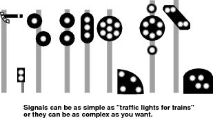
Figure 5-20: Signal Types
The signals heads themselves use LEDs and a mast may have multiple heads mounted on it. Any signal masts you choose can be wired to work with this system. Digitrax builds modular masts that plug into sockets on a ten conductor flat ribbon cable. Multiple masts can be plugged onto each cable. The cable can be run for about fifty feet from the signal controller. Each controller has plugs for eight signal control cables. Signal heads can be three light, searchlight, position light. color position light or various other configurations used outside the US and Canada. Figure 5-20 shows examples of some of these signal heads. Semaphore signals can be driven by using turnout motors and signal lamp outputs.
To make provisions for the future signaling system on the layout discussed here, each signal mast location must be identified to make sure there is a place where the signal mast can be mounted and that none of the benchwork is in the way. Provisions must be made to leave room for the ribbon cables from the foot of the signal masts to the signal controller board. Consideration must be given to where the occupancy detector and signal controller boards will be located so that enough power supplies can be provided at the right locations and so that they can be easily connected to LocoNet.
The detection sections must be located correctly for proper operation of the signals. Figure 5-21 shows the location of the detection sections for a generic section of single track mainline.
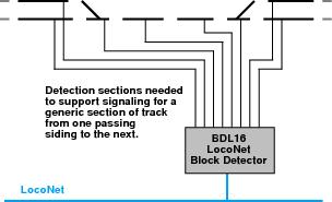
Figure 5-21: Detection sections for signaling