This section discusses the installation of the physical wiring of the Texas & Southwestern.
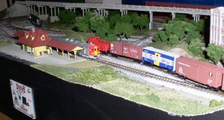
Underneath the completed Texas & Southwestern are various wires and cables which allow you to operate your railroad.
Initially, seeing all these wires can be intimidating, but as you will note, they have been grouped and bundled so that identifying the individual wires is easy. There are two groups of wires under the railroad; one group, the power bus, delivers power to the tracks and to the stationary decoders that operate the track switches. The other group of wires is the black cable for LocoNet and its devices.
Power Bus: The Zephyr is fitted into one corner of the railroad and the various wires are fed through to the bottom of the railroad.
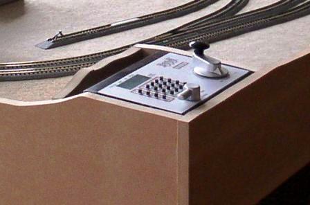
The power bus connects the terminals of the DCS50 Zephyr to the tracks of the railroad and the stationary decoders that are used to operate the track switches.
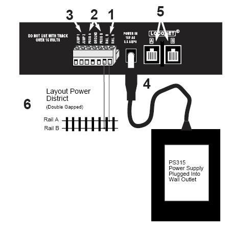
Please note that the protocol used for DCC wiring and the standard colors that Kato uses for its devices are not the same. Clear labeling and tidy wire bundles minimize this possible source of confusion.
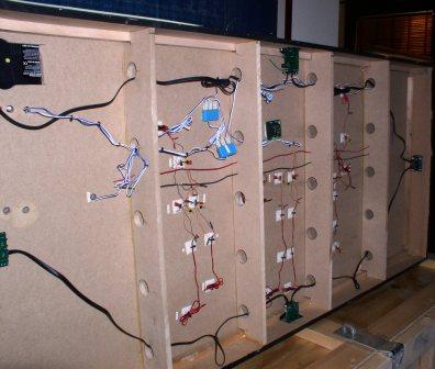
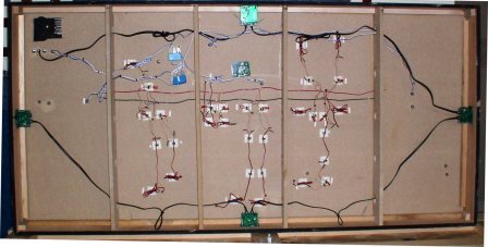
In this bottom view, the blue/white cables are the power bus cables coming from the Zephyr (upper left). As noted in other text, these cables have been split into groups should it later be necessary to subdivide the railroad to add an additional power booster and power supply. In the middle of the railroad is a smaller power bus which uses red and black wires; the stationary DS51K1 decoders are attached to this bus.
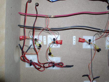
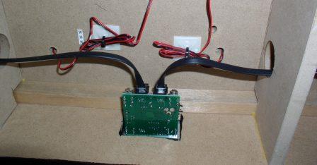
In a close up view, three DS51K1's are first connected to the power bus and then to the turnout which they control. The red and black wires of the DS51K1 are connected to the power bus, while the orange and gray wires are connected to the Kato turnout. Again, a possible source of confusion is that the orange and gray wires of the Digitrax decoder are soldered to the Kato turnout wires, which are red and black. Once the decoders are in place, the turnouts are programmed and small numerical tags are placed to identify each of the DS51K1's. The power bus is also connected to the AR1 Autoreverser, which is discussed separately.
LocoNet: The other key component is the LocoNet. LocoNet allows the addition of throttles, a computer interface and other useful devices.
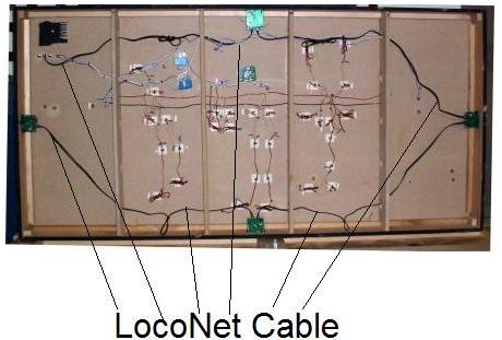
The black cable is the LocoNet cable, which is connected to the back of the Zephyr and the is daisy-chained to the other LocoNet devices; in this case, it is four Universal Panels.
Universal Panels: The Universal Panels allow individual operators to plug into LocoNet to operate trains. From the front, the Universal Panels provide a clean appearance.
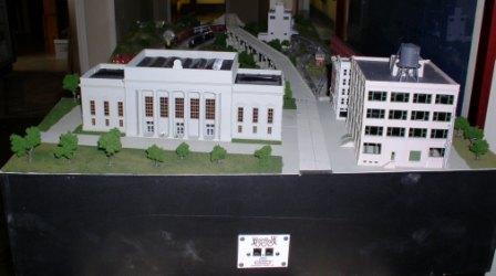
The Texas & Southwestern is fitted out with three UP5s and a UR91. The UR91 allows for tetherless operation, either via infrared or via simplex radio (Use UR92 for infrared or duplex radio operation). Care should be exercised when installing the universal panels to avoid damaging the front graphics. The LocoNet cable is first connected to either LocoNet port of the Zephyr, then connected to one socket of a Universal Panel. The next segment of LocoNet cable is connected to the other socket and then is connected to the next LocoNet device. LocoNet can be arranged in a free-form fashion, but it must never be connected back upon itself by returning to the LocoNet ports of the Zephyr.
The AR1 Autoreverser is discussed separately, under "Reverse Loops".
Many thanks to Mr. Riley O'Connor for sharing the Texas & Southwestern with us!