Braking sections are sections of track which will cause a DCC equipped locomotive to stop automatically.
The simplest way to do this is to set up a track section where the power is turned off. This has two disadvantages. First, since there is no power, the locomotive lights will be off when the train is stopped in the section. Second, the lead loco in a consist stops as soon as it hits the dead section. Other locos in the consist will push the dead loco forward. In a long consist, you could get a situation where the last loco in a consist is still on the powered track but stalled with the wheels slipping, unable to move the dead locos in front of it. This is not good for the loco. Of course if your consist has only a couple of locos this won't be a problem.
One of the internal soft switches in Digitrax DCS100 (Super Chief), OpSw47, configures the independent programming track outputs of the DCS100 as a braking section or stopping track. When these outputs are not being used for programming, a 'set speed to 0' command is broadcast to all locos entering the track segment connected to these outputs. A loco receiving these commands will not necessarily stop dead; instead it will use the momentum value, programmed for deceleration to slow to a halt. If this value is chosen correctly, the complete consist will coast into the braking section. This braking section continues to provide the DCC signal, so the lights and other functions will continue to operate.
To exit the braking section a switch is thrown to re-connect the track section to the normal DCC power bus. When preparing to start again, make sure that the train speed is set to '0' on the throttle that is controlling it or the locos will accelerate immediately to their previous speed according to the acceleration value stored in the decoder. This arrangement shown in figure below.
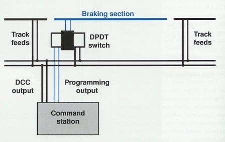
This method can be used to control multiple braking sections. Since the command station's programming output is used to generate the braking commands, it pays to install a separate switch at the command station so that everything on the braking sections isn't programmed by accident.
Another way to handle braking sections is to use automatic analog mode conversion. Many DCC decoders have an internal switch which controls automatic analog mode conversion. By setting up your decoders with automatic analog mode conversion "off' you can create braking sections by using depowered sections. The figure below shows block signals connected to a detector and a relay.
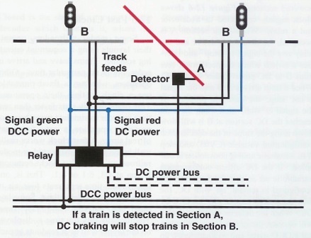
When track section A is occupied, the detector is active and the relay sets the signal to 'stop" and operates a switch which connects track sections B to DC power rather than DCC. When a train arrives at B and the signal is not 'stop,' the train will proceed. If the signal is 'stop,' then when the train reaches the DC section at B it will slow down using the value of the deceleration configuration variable (CV05) and stop if its automatic analog conversion is disabled.
If the DC effects configuration variable is set so that the functions are configured to remain 'on' with DC, the loco lights will remain on, powered by DC. When the detector clears, the relay will operate, the stopped train will again see a DCC signal and will accelerate up to speed and proceed.
Most DC layouts have DC power supplies for accessories and lights so, this method of automated braking can be easily implemented. If the analog mode conversion is turned off in your locos for use with braking sections, then they will not run on DC power. If you plan to use your locos on a DC layout, be sure to reprogram the automatic analog mode conversion feature analog mode conversion "off' back to "on" before you head over to a friend's DC controlled layout.