Product Support for: Command Stations & Boosters -> 8 Amp DCC Command Station & Booster (DCS200)
View the Product Page for the DCS200Big power, Big capacity, for really big fun! The DCS200 Command Station/Booster lets your LocoNet System delivers 8 Amps of power to run up to 120 locos and 120 throttles. Complete with full read/ write programming, route capability, and a separate programming output so you can run and program at the same time. The DCS200 is the most powerful Command Station/Booster we offer and comes as part of our 8 Amp Super Chief Xtra Set or as an add-on to your existing system.
21 Articles Found for DCS200
There is no way to completely reset the Digitrax DCS100 or DCS200 Command Station/Booster using Option Switches such as Option Switch 39. Option Switch 39 resets Locomotive Registry, Consists, etc. associated with DCC equipped locos by resetting mobile decoder info (that is in the command station) and consists, routes and loco roster info. It does not necessarily reset other Option Switches as expected. A complete reset of the DCS100 and DCS200 to factiory defaults is only accomplished by removing input power and removing the battery. This involves disconnecting the grey terminal plug then removing the metal cover by unscrewing the ...
This list is the same for DCS100 & DCS200 Command Stations.* NOTE: Option Switches 36, 37, 38 & 39 have special instructions.
Q: I recently split my layout in half, with a DB150 acting as a booster powering one side and a DCS100 powering the other. I'm trying to reconnect the bus feeders to the rails, which all worked properly before the split. Now when I reconnect the feeders there is no short indication, BUT when a loco goes over the insulated gap between the two sections, a short occurs. A: This is a common issue when the first booster is added to a DCS100/DCS200 command station. MOST DCS100/DCS200 command stations come from the factory set with Rail A & Rail B connections that are the opposite ...
Instructions below are for both DCS100 & DCS200 (DCS200 omitted in text for clarity).1. Refer to the DCS100 Option Switch Table to decide which option switches you want to change. Also note that there are special instructions for OpSw's 36, 37, 38, & 39. 2. Move the MODE toggle switch on the front of the DCS100 into the "OP" position . The LocoNet Railsync will go inactive & all other boosters plugged in to LocoNet, including the one that is built into the DCS100, will shut down. 3. Disconnect LocoNet from the DCS100 you are configuring. 4. Connect your DT300 ...
Note: These instructions are the same for DCS100 & DCS200 (DCS200 omitted for clarity).1. Refer to the DCS100 Option Switch Table to decide which option switches you want to change. Also note that there are special instructions for OpSw's 36, 37, 38, & 39. 2. Move the MODE toggle switch on the front of the DCS100 into the "OP" position . The LocoNet Railsync will go inactive & all other boosters plugged in to LocoNet, including the one that is built into the DCS100, will shut down. 3. Disconnect LocoNet from the DCS100 you are configuring. 4. Connect your DT400 ...
You can use your DT400 series throttle with a DCS100 or DCS200 to set up routes that are triggered by operating a single turnout address to make it either c (closed) or t (thrown). Setting up and operating routes is similar to consisting locomotives because you can cause more than one unit to operate based on a single command sent to the system. We call the turnout address that other turnout addresses are “consisted” to, the TOP address. To operate a route, use Sw (Switch) mode to select the TOP turnout address in the route and move it to either closed or ...
The DCS100, 200, 240 and DB150 use several beeps and clicks that can be used as diagnostic tools that will help you debug a number of error conditions. DCS100/200 Audible Sounds 1 Beep DCS100/200 has powered on successfully or has sent a programming command. 3 Beeps A loco address has been "purged" due to non-use. This is informational only and is normal. 4 Beeps Booster short circuit shutdown. Fault Alarm. 6 Beeps Command station already present in system. When two command stations are operating on the same system, you may experience unexpected results. 7 Beeps DCS100/200 CMOS battery low ...
The two "POWER IN" terminals on all Digitrax boosters & command stations are the power input connections. Digitrax recommends the PS514 to power the DC200 and DB150. Set the voltage setting on the PS514 to 16.8v or 19v. The PS2012 can also be used to power the DCS100 and DB150. The "Y" cable provided with the PS2012 has an embedded 5 amp current protection. The PS2012 can also be used to power the DCS200. The "Y" cable is not suitable for use with the DCS200 since it has an 8 amp. output. When powering your layout, make sure that all polarities and ...
When using a DCS100 or DCS200 to setup routes within the Command Station in conjunction with DS64 Stationary Decoders, the DS64 needs to be connected to Track Power. The DCS100/200 does not send internal route messages via LocoNet. DCS100/200s only send Routes as a series of switch commands out to the Track in DCC format. The DSC100/200 were designed in 1996 and had no requirement to echo these same switch commands out via LocoNet. Additionally, DS64 Stationary Decoders are designed to allow up to 8 Routes to be programmed internally into them. Please refer to the DS64 manual and other ...
I have read that the amperage of the power supply should match the amperage rating of the booster / command station. Yes, from the standpoint of putting more than 8 Amps of power into an 8 Amp Chief is not going to make a difference since only 8 Amps is going to come out. Less than 8 amps in is only going to result in that same amount (roughly) out; thus, a 5 Amp power supply will only yield 5 Amps out, even though the system is rated at 8 Amps. The DCS200 Super Chief is rated at 8 amps. ...
This document outlines the power requirements for Digitrax LocoNet accessories. To simplify wiring, Digitrax recommends providing individual power supplies for like accessories. For example a power supply or power buss which only powers the PM42s. A power supply or power buss used solely to power multiple DS64s. UR9x and UP5 panels can be daisy chained provided adequate current is provided to properly power all the panels. Through the use of individual power supplies, the chance of Ground Loops or sneak paths back to ground is minimized. Using individual power supplies will also make troubleshooting much easier. Many Digitrax LocoNet ...
Many clubs use a DCS100/200 as a Booster in their setups. Digitrax does not recommend using a DCS100/200 as a Booster only for this type of setup. If you decide to do so, please keep this information in mind: The DCS100/200 configuration is stored in memory that uses a CR2032 battery. Over time the battery can get weak and the DCS100/200 will loose its ability to store its configuration. When this happens, the DCS100/200 will sound 7 beeps at power up. It will also revert back to its factory settings and once again become a Command Station. Since LocoNet ...
Q: How do I program the PM42 Option Switches (OpSw) with a DT400 throttle? A: The PM42 OpSw settings are used to set up the PM42, adjusting the trip current, short circuit management (including sensitivity), and/or auto-reversing. Note: The factory default setting on all PM42 OpSws is “thrown” or “t”. Follow the steps outlined below to program the OpSw settings of the PM42 using the DT400 series throttle with any Digitrax command system. 1) Connect the PM42 to a DCS50, DCS51, DB150, DCS100, or DCS200 with a standard LocoNet cable. 2) Connect the PM42 to an external power source; Digitrax ...
Q: I just purchased a used Digitrax set consisting of a DB150, UT2 and a PS515 for a very low price. What do I need to add to bring this up to current standards? A: Because of Digitrax LocoNet, it is easy to add the latest components to upgrade on older starter set. What you purchased was originally called a Genesis Starter Set. The PS515 did not come with it but it is the perfect power supply for the DB150. Your next step depends on what you want to do with your railroad. In this case, the components you have will be ...
Before sending your Digitrax Command Station or Booster in for repair try these simple steps to see if you can “bring it back from the dead” and save a possible trip to the repair shop.1. Nothing is respondingIf there are NO LEDs lit on the front panel of the Command Station or Booster: Check the power supply to the unit to make sure that it has not been knocked loose in the power socket and that the socket is powered. Check the connections from the power supply to Track A and Track B connections on the front of the unit ...
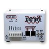
The 5 Amp DCS100 and the 8 Amp DCS200 share the same front panel layout. There is a variety of indicators, switches and connectors: Power Input The two POWER IN terminals on all Digitrax boosters & command stations are the power input connections. Power On Indicator This green LED indicates that the power to the DCS100 is on. Ground Terminal The terminal marked ground provides electrical safety features and an RF ground reference for minimum radiated noise. This should be the ONLY point of any DCS100 installation that is connected to the AC safety ground pin provided on most 3 ...
Programming is the process of setting the configuration variables (CVs) in your decoder to the appropriate values that will make the locomotive perform the way you want it to. The first CVs that most people change are those that set the locomotive decoder's address. The mobile decoder in your locomotive usually comes pre-porgrammed to a factory default address of "03". Once you add a second locomotive, you will want to change the this new locomotive to another address. Not doing so will result in both locomotives operating at the same time when you send commands to address 03.Likewise, there are a ...
The DT402 & DT400 can program and readback CVs with the DCS100 or DCS200 (Super Chief) or the DCS51 or DCS50 (Zephyr). You must use the programming track for this unless you are using Ops Mode with transponding installed to allow for Ops Mode readback. Infrared and simplex radio throttles must be plugged in to LocoNet to read back CVs & their values. Duplex radio throttles do not have to be plugged in for reading back CVs.Systems with a DB150 command station (Super Empire Builder) are not able to read back CV Values programmed into decoders. To read back CV values: 1. Place the decoder ...
Duplex Radio Throttle do not need to be plugged in to LocoNet to Program Decoders. Simplex Radio & Infrared throttles must be plugged in to LocoNet to program CVs on the programming track. Ops Mode Programming can be done without plugging radio throttles in to LocoNet. IR throttles must be plugged in for Ops Mode Programming. 1. Be sure that only the loco you want to program is on the programming track. If you are using operations mode programming, the loco you want to program can be anywhere on the layout but it must have a decoder that is ...
The PS615 is the Digitrax recommended power supply for the DCS240 in 5 amp mode. For operations at 8 amps the PS2012 is the recommended power supply. When using the PS2012 special wiring considerations need to be used when powering both the DCS240 and legacy boosters from the same PS2012. Leagacy boosters are defined as the DCS100, DCS200, DB150, DB200 or DB100. Please see the separate article “Powering your DCS240 with a PS2012” and the additional notes below. The DCS240 may be powered either using the barrel plug connector or the screw terminals labeled “+” and “- “. The barrel ...
This article stops in a strange place?? We need to find the rest of it and split it up into meaningful chunks. Also needs meta stuff Troubleshooting in General:Regardless of the guides, manuals, tips, suggestions, experts or whatever, troubleshooting can occasionally degenerate into a vast chasm of darkness and confusion. It would be impossible to cover all the areas that have, can or may cause problems. This is a general guide to identifying and resolving problems with Digitrax Complete Train Control. Keep Good Records:Although it may seem to be a pain while setting up your Digitrax system, keeping layout records ...