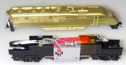
The Athearn N-Scale P59PHI was not designed for a plug 'n play or board replacement installation therefore, a wired installation will be necessary. This installation is straightforward if you follow the instructions provided below. There is plenty of room inside the locomotive for this installation.
Athearn N-Scale P59PHI Installation Instructions for Digitrax Decoders:
1. Remove the locomotive's shell. Note which end of the frame is the front and which is the back.
2. Remove the light board that is installed on the top of the frame. Do this by removing the cylindrical black spacers and lifting the board out of the locomotive.
3. Remove the metal contact strips that run from the top of the locomotive to the motor brushes on each side of the gray case that holds the motor.
4. Use a sharp knife to remove the gray plastic bars from across the openings on each side where the metal tabs were removed to leave room for routing the wires from the decoder to the pickup tabs and brush contacts.
5. Place the decoder on top of the frame in the area where the light board was located.
6. Cut the red and black wires slightly longer than the distance needed to reach the brass track pickup tabs at the bottom of the slot below the motor brush contacts, bend the pickup tabs in slightly and solder the red wire to the right side (engineer's side) tab and the black to the left side. Be careful that there is no contact created between the brass pickup tab and the motor brush contact when you solder the wires in place. The insulation on the wires should extend below the brush caps to prevent contact with the brass pickup tabs.
Cut the orange and gray wires slightly longer than the distance from the decoder to the motor brush contacts and very carefully solder the orange wire to the right side and the gray wire to the left side motor brush contacts. Again make sure there is no contact between the motor brush contacts and the brass pick up tabs.
Secure the decoder and wires with tape across the top of the locomotive frame.
To install the lights in the locomotive, you can remove the LEDs and the resistor from the light board that came with the locomotive and install them with your decoder. You can also install white LEDs if you wish. Use the decoder's white and blue wires for the front light and the yellow and blue wires for the rear light. Cut the blue wire and install the resistor in line between the decoder and either LED. Use shrink tubing around all solder joints to protect against shorting wires to the frame of the locomotive.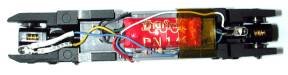
Top View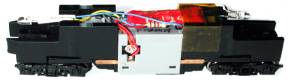
Side View