The DB200+ is the 8 amp booster. It has NO command station capability. This booster was designed for adding power to layouts that run lots of locos and for large-scale layouts where power requirements are heavy.
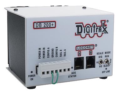
DB200+ Control Panel
NOTE: DB200+ front panel graphics may vary from those shown here. Internally the booster is the same. These instructions are written for both versions of graphics as well as the DB200+ OPTO optoisolated version of the booster.
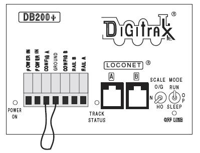
About the Green Jumper Wire
Every DB200+ is shipped with a green jumper wire on the front panel Booster Terminal Plug connecting Synch & Ground or ‘Config A’ & Ground. This jumper is needed for proper operation. Do not remove it. This jumper is needed for proper operation. There are no connections to 'CONFIG B'.
Power Input
The two “POWER IN” terminals on the DB200+ booster are the power input connections. Connect 8amp current limited input power to these terminals.
Digitrax recommends the PS2012 20amp power supply to power the DB200+. The PS2012 can power up to two DB200+ boosters. We recommend separate inline fuses or circuit breakers rated at 8amps.
NOTE: The 'Y' power cable included with the PS2012 has 5amp self resetting current limiters and should NOT be used for powering the DB200+.
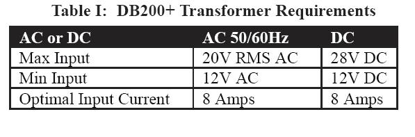
Please refer to Table 1 for transformer requirements.
For proper operation the DB200+ case should be connected to the case/common ground of the command station and any other boosters or devices requiring a common ground.
Heat Dissipation
It is normal for the DB200+ to be warm to the touch when it is in use. It is designed to absorb and dissipate the power difference between the input voltage and the selected scale output voltage, at the current load being drawn. If the unit is not able to dissipate excess heat, over-temperature thermal shutdown may occur. We recommend that you locate the boosters where they can dissipate heat. If you experience frequent over temperature shutdowns, add a small fan to help cool the booster.
Power On Indicator
This green LED indicates that the power to the DB200+ is on. It should glow steady green.
When powering up your Digitrax system, we recommend that the command station be turned on first and allowed to stabilize. Power on any boosters next and finally any additional devices such as PM42, BDL168, or SE8C.
RAIL A & RAIL B Terminals
Connect these terminals to the track or power management device. For smaller scale layouts, Digitrax recommends using the PM42 to provide proper power management. When making track connections, ensure that Rail A and Rail B are connected to the same terminal on each booster, for example connect all Rail A terminals to the right rail and all Rail B terminals to the left rail or vice-versa on all track sections.
TRACK STATUS Indicator
The “TRACK STATUS” indicator shows that there is voltage on RAIL A & RAIL B terminals. Under normal conditions, the indicator will glow orange. If an analog locomotive is being run on the layout, the indicator light will be either green or red. ALL booster "TRACK STATUS" indicators should be the same color.
OFF LINE Indicator
The DB200+ automatically shuts down when the booster temperature rises to around 45 to 50 degrees Celsius (113 - 122 degrees Fahrenheit) and the “OFF LINE” indicator will glow red. The DB200+ automatically resumes operation once the DB200+ cools down.
LocoNet Jacks A & B
Connect either Loconet Jack A or B to your existing Loconet. These jacks let you easily expand your Digitrax system by simply plugging other LocoNet devices into the system.
MODE Switch
The 3 MODE switch settings are:
RUN is for normal operations.
P/R or OP is used to enable the DB200+ for Auto Reversing (see below)
SLEEP is used to shut down the system.
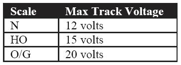
SCALE Switch (0/G H0 N)
This switch sets the maximum track voltage limit.
Track Voltage Adjustment
The actual track voltage supplied by the DB200+ can be adjusted. In most cases, you will not have to make any adjustments.
To determine the actual track voltage, measure the DC voltage (unloaded) from either the RAIL A or B Terminal to the green ground wire on the case. Multiply the measured voltage by 2 to determine the approximate digital track voltage supplied.
If the DB200+ output voltage is not within .2 volts of other boosters, then proceed as follows:
In order to make a voltage adjustment, you must open the DB200+ case (this will not void your warranty).
1. Remove the DB200+ input power and Terminal Booster Plug.
2. Remove the two screws on the top and bottom of each side of the case.
3. Slide the gray front panel off the DB200+
4. Be careful to avoid disturbing components other than the ones described below.
5. Reconnect the Terminal booster Plug and LocoNet cables to the DB200+.
6. Reapply power to the DB200+.
7. Locate the small yellow trimmer potentiometer behind the LocoNet B Jack and the Scale Switch.
8. Use a small screwdriver to turn the potentiometer either clockwise to increase track voltage or counter clockwise to decrease track voltage.
9. Once you are satisfied with the voltage setting, reassemble the DB200+.