DN163K0b Installation Instructions for Kato F-3, F-7
1. Carefully remove the locomotive’s shell from the frame.
2. Remove the black plastic cab seat panel by gently pressing in at the sides.
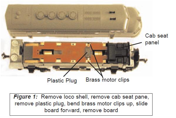
3. Carefully remove the plastic plug that retains the brass motor clips and bend the brass motor clips up and away from the circuit board.
4. Slide the circuit board forward to release it from the clip on the locomotive frame and lift the board off the frame.
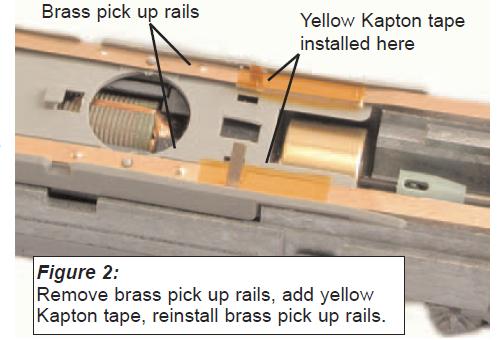
5. Remove the brass pickup rail from one side of the locomotive, being careful not to bend it. Wrap a small piece of yellow Kapton tape (supplied with the Digitrax decoder) around the rail just to the front of the dimple (between the dotted lines in photo, right). The tape should wrap around the outside edge to ensure the brass motor clip is completely isolated from the brass pickup rail when it is reinstalled. Trim excess tape on the INSIDE edge of the brass pickup rail and reinstall it in the locomotive, lining it up over the position pin. Repeat the process for the other brass pick up rail. (Figure 2)
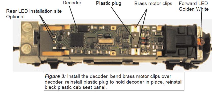
6. Install the decoder between the motor clips. Press down and slide the board back to lock the board under the plastic clip in the frame. Be careful to keep the brass pick up rails in position.
7. Bend the motor clips down over the pads on the decoder making sure the Kapton tape insulates them from the brass pick up rails. Reinstall the plastic clip to hold the motor clips tightly against the pads of the circuit board and the circuit board in place. If the plug is not secure, add a piece of tape to secure the decoder against the motor clips. To ensure good contact you may want to add some solder to the motor clips as the plastic plug is often too loose.
8. Reinstall the black plastic cab seat panel over the head light.
9. Place the locomotive on the track, select address 03 on your throttle and apply power. If the motor does not respond but you can control the lights, check the installation for motor short circuits. For this installation, be sure the Kapton tape is preventing contact between the brass pick up rails and the brass motor clips.
NOTE - If installing in a cabless B unit, the LED headlight can be removed.
10. Replace the locomotive shell.
11. Digitrax decoders are set up with configuration variable (CV) default values so you can run your locomotive right away using address 03.