While it is possible to use RJ12 telco jacks as throttle jacks on LocoNet, the UP5 is much simpler to use and looks much more professional on the front of the layout.
The UP5 is shipped as a kit that must be assembled. You will need to attach the front panel to the circuit board using the screws provided as shown below before installing the entire unit on your layout. If your front panel does not fit at a "perfect" 90 degree angle to the circuit board, this is will not affect the functionality of the unit.
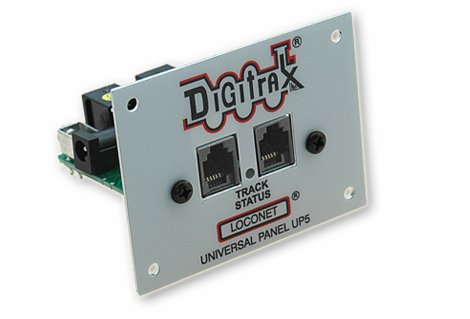
Make sure to line up the Track Status LED with the front panel when assembling the unit. If the LED should face the front panel for correct operation. The black screws are used to attach the front panel to the circuit board. The silver screws on the back of the circuit board are used for track connections.
The RJ12 jacks on the back of the unit are used for daisy chaining from one LocoNet device to the next on the layout.
The RJ12 jacks on the front and sides of the UP5 should be used ONLY as throttle jacks.
