Preparation
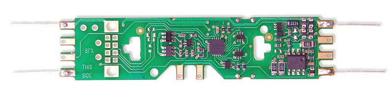
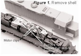
1. Carefully remove the locomotive's shell from the frame.
Note the orientation for proper reinstallation. (Figure 1)
2. Remove the four track power pickup wires clipped to the lightboard (2 on each side) (Figure 2)
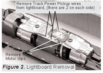
Carefully pull the brass motor clips from under the track power "staples" on the lightboard.
3. Unscrew the lightboard screws to release PCB from the frame.
Decoder Board Installation
4. Physically secure the DH165K0 decoder PCB with the lightboard screws.
5. Attach the four track power pickup wires by shortening and stripping each wire (2 on each end) and soldering these wires to each corner of the decoder PCB as shown (Figure 3)
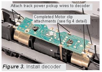
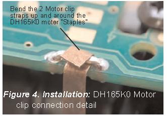
6. Reattach the brass motor clips through the motor "staples" on the decoder (Figure 4).
7. Solder white LEDs at the alternate F0 location in PCB center and at locomotive rear.
The LED anodes/+ go to "blue" pads.
You can use the original LEDS.
8. Replace the locomotive shell.