The Kelana Jaya Rail Line model layout uses WinLok 2.1 running on a PC under Windows 98 to operate the trains, turnouts, signals and to use the feedback from the block detectors for train control.
This equipment was configured and programmed to PUTRA's specifications by Dr. Hans R. Tanner of DigiToys Systems. PUTRA specified the following capabilities for the control system used for the simulation: 1. Run eight trains at once in any combination of automated or manual control. 2. Define specific routings and be able to assign automatically or manually any route to any train at the time the train is dispatched from its terminal. 3. Protect interlocked train movements for every train on the layout, irrespective of its control method, automatic or manual. 4. Emulation of manual operation and communication for the simulation of train breakdowns and other emergencies. 5. Simulation of dispatching of trains to and from the maintenance facility. 6. Simulation of the prototype CTC-like control panel. To meet these requirements, WinLok combines four basic programming elements:
- CTC panel and logic
- Routes
- Signals and security flags
- A timetable
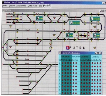
The CTC Panel The first element is the CTC panel and its associated controls. The PUTRA CTC panel as a whole appears below:
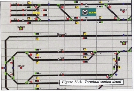
This section of computer panel controls the stub terminal trackage:
The track layout:
All of the buttons, controls, lights and indicators on this panel are simulated by the WinLok software. Each track segment has its own occupancy detector. Every track segment must have its type defined for the CTC panel. In particular all halting points are identified and numbered. These are places where a train is permitted to stop under normal circumstances and where it does not foul turnouts. For example, on Figure 11-5, El, Tl and Bypass 2 are all halting points. The CTC panel also includes block signal controls, occupancy detector feedback and numbered turnout controls. Also provided are a set of colored route selection buttons which control route establishment. Special control buttons are provided to hold trains at any halting point and to send trains automatically to their staging point for the next day. PUTRA shuts down at night. To simplify movements in the morning, four trains are staged at each end of the line: four in the EI-E4 tracks at the stub terminal and four at the yard complex. On the computer display panels, the yellow buttons by each halting point are used to show and control the reservation status of that section and can be used manually to reserve or release that segment of track. The blue buttons below the halting points toggle the direction of travel flag for the track. A blue arrow appears next to the button if the track has been set for a particular direction of travel. The block signals could be operated manually by the green button next to them. The turnouts are operated by the white numbered buttons next to them and the turnout state (thrown or closed) is shown on the track diagram. The red and gray buttons associated with the halting points are used to control train routes. Usually, the red button commands an eastbound route and the gray button commands a westbound route. These routes are commanded on a 'from'/'to' basis, so that two buttons must be pressed for the route to operate. This provides valuable security against accidental route selection. The 'Stack It' special button is used to park trains at the end of the line for the next day. The Run/Stop button will send all trains to the yard for manual storage if set to Stop. Routes The second element is the underlying framework of routes. These routes are defined for every permissible train movement. Each route consists of smaller elements that run from halting point to halting point. Each halting point has a switch for reservation or occupancy and for direction of travel. Track segments between halting points have a switch which describes the desired direction of movement. From these components a route is assembled. When a route is activated, the direction switch is set for all other track sections for the duration of the train movement. All other direction switches are set for other tracks to protect against routes which might cross the selected route. The turnouts are then set for the requested route starting with the most distant turnout. Finally, the most distant available halting point is reserved. As the train travels along the route, it clears control of the various track segments it has used. If necessary, the trains will wait at a halting point for the route ahead of it to become available. Interlocking is handled by the CTC panel configuration and the security flags. The software prevents a 'deadlock' condition where two trains try to grab control of the same section of track at exactly the same time so that neither can take control. It also prevents a 'deadly embrace' where two trains each control a section of track that the other one needs, but neither can release the track it has until it gets control of the other train's track Signals and Security Flags Dwarf signals reflect the turnout state and the block signals are provided for visual feedback of the state of the next block. The signals are controlled by the CTC panel logic and the track occupancy detectors. The security flags are used for the reservation and occupancy status of track segments and to ensure that the train is traveling on track reserved for it in its actual direction of travel. Security flags also protect other track and routes which are temporarily unavailable while a particular route is active. The PUTRA prototype uses signals which default to green. Thus, if a track section is not occupied and has no 'preset direction, then both eastbound and westbound signals will show green. Signals will show red if the next track section for that direction of movement is occupied or if the switch at the end of the block is aligned against the direction of travel. Timetable Figure 11-6 shows the timetable configuration panel:
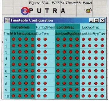
The display shows the configuration capabilities for ten individual trains, one train on each row of the panel. The first band of columns defines the behavior of the train in the Kelana Jaya station area if the train is approaching from the Dang Wangi station. Possible options according to the required routes of the PUTRA system are: 1. Use middle track of University, change direction and return to Dang Wangi. 2. Use any free track at Kelana Jaya, change direction and return to Dang Wangi. 3. Use any free track at Kelana Jaya and proceed to C tracks in Yard using the reversing loop. 4. Use any free track at Kelana Jaya and proceed to S tracks in Yard using the reversing loop. The second band of columns defines the behavior of a train at Terminal station if the train is approaching from Seri Rampai. Possible options are: 1. Use any free track at Terminal, change direction and return to Seri Rampai. 2. Use any free track at Terminal, then proceed to storage in any of E1 to E4. The remaining bands of columns control other locations. The locomotive timetable controls the movement of the assigned train. It establishes the routing for that train, the first available train at a given location for an available route. The train will then move and stop according to the timetable. All trains are able stop at all stations, but they are not required to do so. If a train is being operated manually, the operator uses a DT100 hand held throttle to control the model. The system dispatcher controls the track using the CTC panel displayed on the computer. The following sequence of operation is followed: 1. The train operator radios the dispatcher requesting permission to proceed to the next station. 2. The dispatcher sets up the route to that station using the 'from' and 'to' route buttons on the panel. 3. The dispatcher gives permission for the train to proceed and the operator acknowledges. 4. The train is moved to the destination and the operator radios to the dispatcher when it arrives there or otherwise stops for any reason. This discussion provides a brief overview of the PUTRA system. It illustrates how computer control and CTC in general can be implemented using WinLok and DCC. Several DCC software packages are available that will accomplish the same tasks shown here. You may find a software package that is better suited to your needs but you will find that the principles used here can be applied to almost any model railroad application. In this layout, the only connection between the computer and the layout is the LocoNet cable. Since the CTC board is a computer simulation, no other wiring between the layout and the computer is necessary
Part 5 of 5
Information originally printed in The Digitrax Big Book of DCC